Ultrasonic diagnostic apparatus

Inactive Publication Date: 2009-11-26
FUJIFILM CORP
View PDF3 Cites 13 Cited by
  • Summary
  • Abstract
  • Description
  • Claims
  • Application Information

AI Technical Summary

Benefits of technology

[0015]According to the one aspect of the present invention, by obtaining acoustic velocity values with respect to the plural first regions according to a determination result of the focusing determining means and further obtaining acoustic velocity values with respect to plural second regions s

Problems solved by technology

Since the acoustic velocities are different depending on tissues within the object, there are problems that defocusing occurs in reception focusing processing and/or transmission focusing processing, the resolving power becomes lower, and image blurring occurs.
However, if the optimum acoustic velocities are obtained in the small regions, there are prob

Method used


Image

  • Ultrasonic diagnostic apparatus
  • Ultrasonic diagnostic apparatus
  • Ultrasonic diagnostic apparatus

Examples


Embodiment Construction

[0024]Hereinafter, embodiments of the present invention will be described in detail with reference to the drawings.

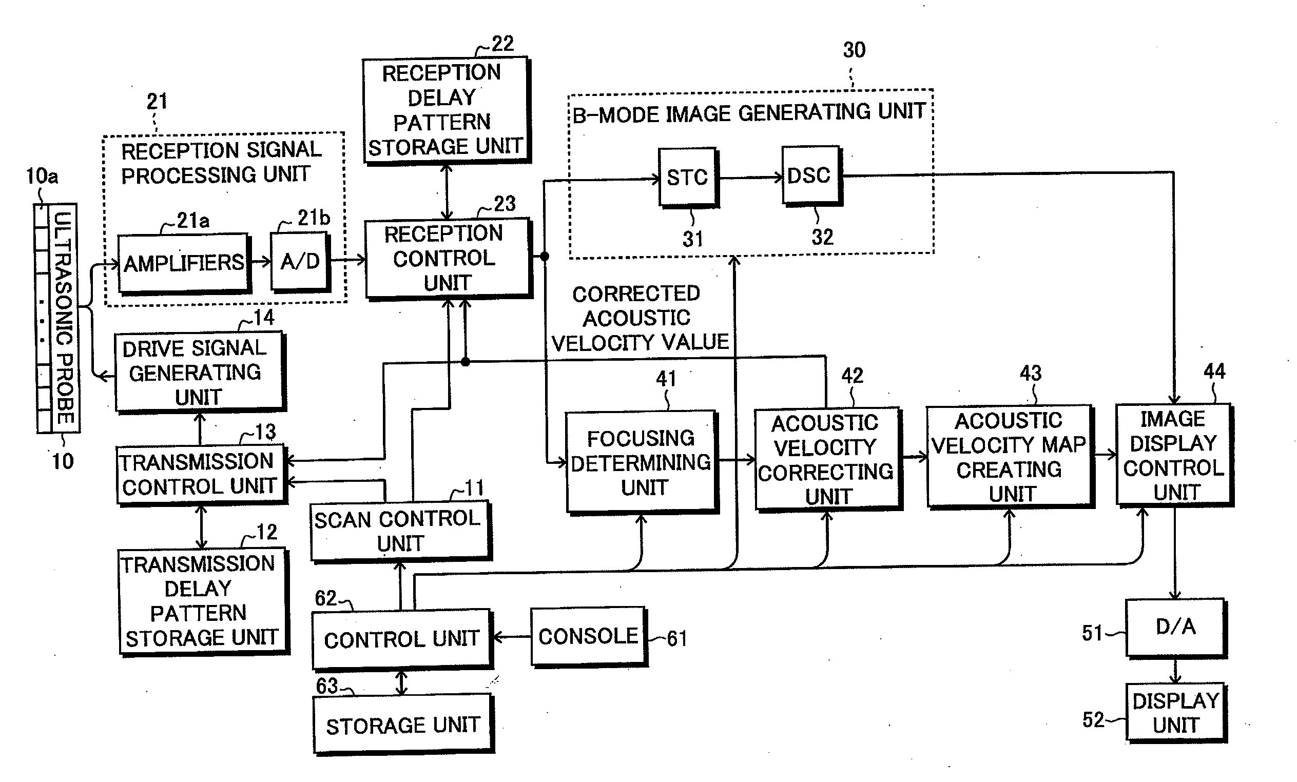
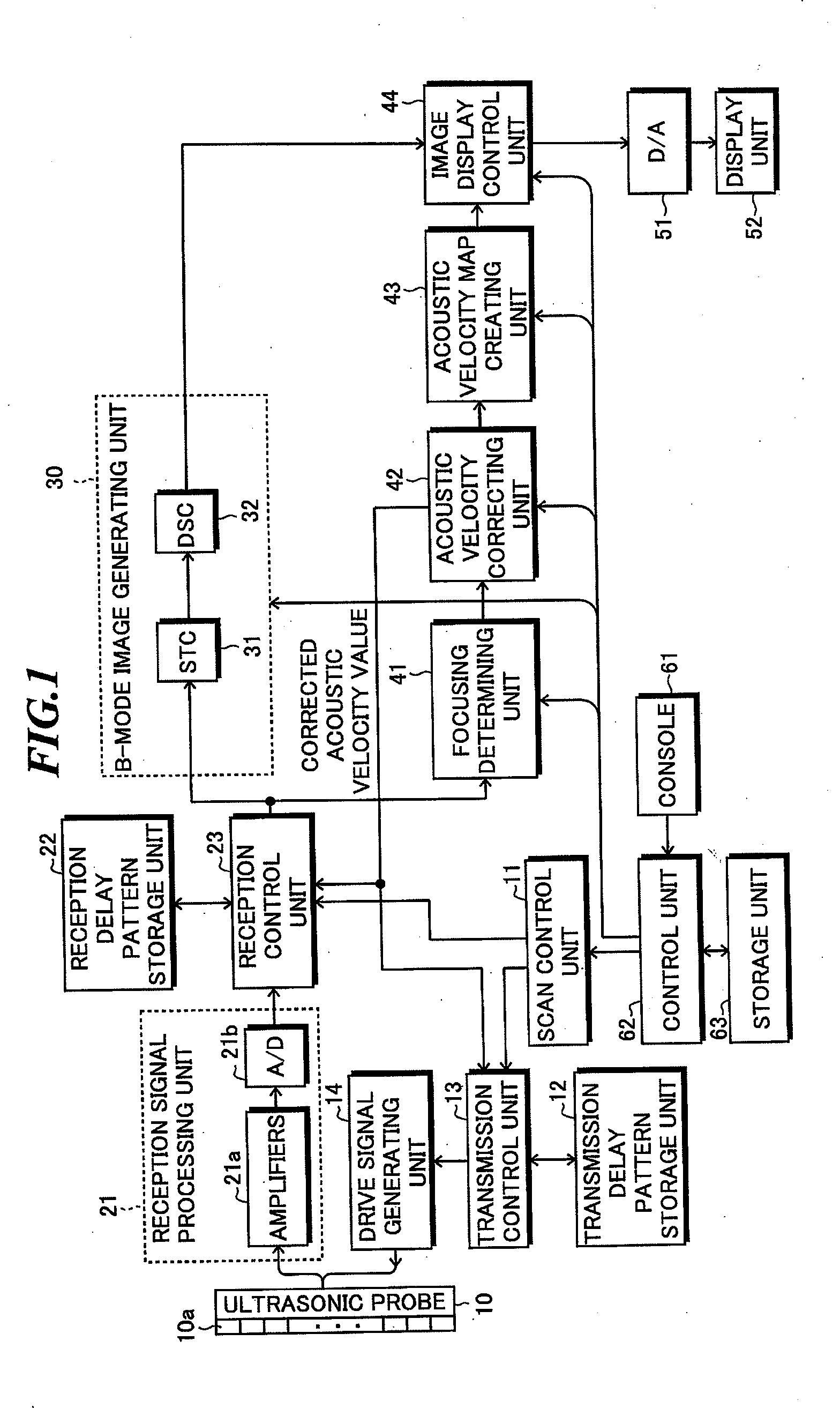
[0025]FIG. 1 is a block diagram showing a configuration of an ultrasonic diagnostic apparatus according to one embodiment of the present invention. The ultrasonic diagnostic apparatus includes an ultrasonic probe 10, a scan control unit 11, a transmission delay pattern storage unit 12, a transmission control unit 13, a drive signal generating unit 14, a reception signal processing unit 21, a reception delay pattern storage unit 22, a reception control unit 23, a B-mode image generating unit 30, a focusing determining unit 41, an acoustic velocity value correcting unit 42, an acoustic velocity map creating unit 43, an image display control unit 44, a D / A converter 51, a display unit 52, a console 61, a control unit 62, and a storage unit 63.

[0026]The ultrasonic probe 10 includes plural ultrasonic transducers 10a forming a one-dimensional or two-dimensional transducer arr...


PUM


Abstract

An ultrasonic diagnostic apparatus in which degradation in calculation accuracy and increase in calculation time can be prevented while an ultrasonic image with high resolving power is generated by using appropriate acoustic velocities for respective regions within an object. The apparatus includes: a transmitting and receiving unit for processing reception signals; a reception control unit for performing focusing processing based on acoustic velocity values to generate a sound ray signal; an image generating unit for generating an image signal based on the sound ray signal; a focusing determining unit for determining a degree of beam focusing in the focusing processing with respect to plural first regions; and an acoustic velocity value correcting unit for obtaining acoustic velocity values with respect to the plural first regions and further obtaining acoustic velocity values with respect to plural second regions segmented in smaller regions than the plural first regions.

Description

BACKGROUND OF THE INVENTION[0001]1. Field of the Invention[0002]The present invention relates to an ultrasonic diagnostic apparatus for imaging organs within a living body and so on by transmitting and receiving ultrasonic waves to generate ultrasonic images to be used for diagnoses.[0003]2. Description of a Related Art[0004]In medical fields, various imaging technologies have been developed for observing inside of an object to be inspected so as to make diagnoses. Especially, ultrasonic imaging for acquiring interior information of the object by transmitting and receiving ultrasonic waves enables image observation in real time and provides no exposure to radiation unlike other medical image technologies such as X-ray photography or RI (radio isotope) scintillation camera. Accordingly, ultrasonic imaging is utilized as an imaging technology at a high level of safety in a wide range of departments including not only the fetal diagnosis in obstetrics, but gynecology, circulatory syste...

Claims


Application Information

Patent Timeline
IPC IPC(8): A61B8/14
CPCA61B8/14
Inventor KARASAWA, HIROYUKI
Owner FUJIFILM CORP
Why Eureka
Try Eureka