
Solver for hardware based computing

Inactive Publication Date: 2009-11-26
DREXEL UNIV
View PDF7 Cites 29 Cited by
  • Summary
  • Abstract
  • Description
  • Claims
  • Application Information

AI Technical Summary

Benefits of technology

[0018]According to a fifth aspect of the current invention, a generator model using analog circuits is developed for load flow emulation for power system analysis to reduce computation time. The generator model may include reconfigurable parameters using operational transconductance amplifiers (OTAs). The circuit module is used with other reconfigurable circuits, i.e., transmission lines and loads.

Problems solved by technology

Currently, power flow computation for large power systems is time intensive.
This presents a problem as many assumptions and simplifications are required to solve the equations in a timely manner.
In addition, expansion of the power grid, increasing necessity and complexity of contingency studies and introduction of economic analysis are demanding further computational burden.
Traditional digital methods are too slow to solve the aforementioned demands quickly.
This affects the security, reliability and market operation of power systems.
The bottleneck in Newton power flow iteration is the solution of a sparse system of linear equations, which is required for each iteration, and typically consumes 85% of the execution time in large-scale power systems [1].
Attempts have also been made to increase performance through the use of cluster computing [1], however, due to the irregular data flow and small granularity of the problem these methods do not scale very well.
Traditional digital methods are expensive and slow in comparison to analog computers.
Without clearly defined valid models for power system components, the analog computational method will never be realized.
The transistor level simulation (bottom-up design), comparatively, can be very tedious and cumbersome especially for mixed-signal chips containing a large number of analog components.
The problem is that such analyses solve using a sequential method, which makes the simulation process very slow in complex networks.
Using an analog VLSI chip can be limited if the fabricated chip is only useful for one power system configuration.

Method used


Image

  • Solver for hardware based computing
  • Solver for hardware based computing
  • Solver for hardware based computing

Examples


Embodiment Construction

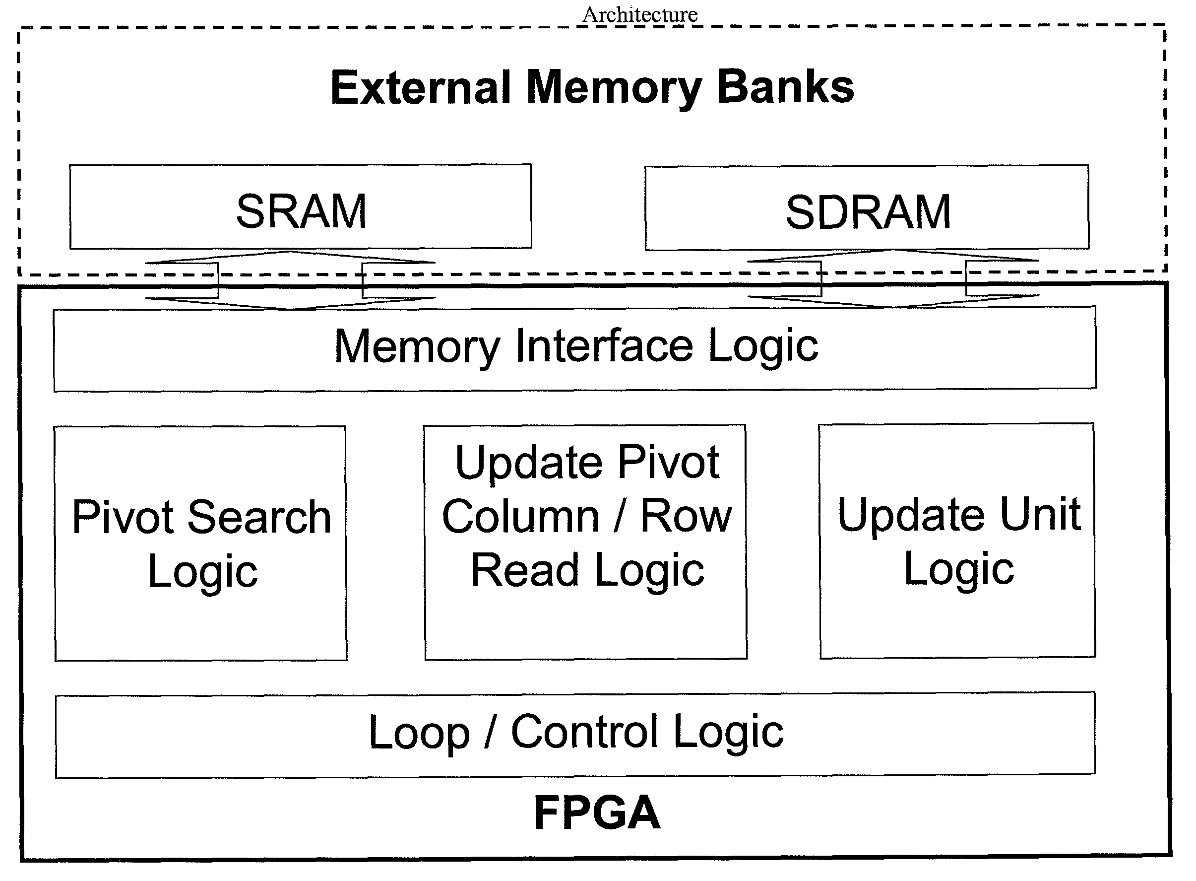
[0063]In the current invention, application-specific hardware is employed to reduce the computation time for the solution of the sparse linear systems arising in complex computations. The use of special-purpose hardware reduces the overhead costs, better utilizes floating-point hardware, and provides fine-grained parallelism. The use of Field Programmable Gate Arrays (FPGA) provides a convenient platform to design and implement such hardware. By building hardware that is specifically designed to solve the sparse matrices found in complex calculations, such as power system calculations, rather than utilizing general-purpose processors and parallel processing, the present invention significantly improves the efficiency of the linear solver and hence reduces the computing time compared to traditional platforms.

[0064]Thus, one aspect of the present invention relates to hardware for the direct solution of sparse linear systems. The hardware design takes advantage of properties of the mat...


PUM


Abstract

Full-AC load flow constitutes a core computation in power system analysis. The present invention provides a performance gain with a hardware implementation of a sparse-linear solver using a Field Programmable Gate Array (FPGA). The invention also relates to the design, simulation, and hardware verification of a static transmission line model for analog power flow computation. Operational transconductance amplifiers are employed in the model based on a previously proposed DC emulation technique of power flow computation, and provide reconfigurability of transmission line parameters via transconductance gain. The invention also uses Analog Behavioral Models (ABMs) in an efficient strategy for designing analog emulation engines for large-scale power system computation. Results of PSpice simulations of these emulation circuits are compared with industrial grade numerical simulations for validation. The application is also concerned with the development of a generator model using analog circuits for load flow emulation for power system analysis to reduce computation time. The generator model includes reconfigurable parameters using operational transconductance amplifiers (OTAs). The circuit module is used with other reconfigurable circuits, i.e., transmission lines and loads.

Description

BACKGROUND OF THE INVENTION[0001]1. Field of the Invention[0002]The current invention is related to a programmable linear algebraic solver for large sparse matrices based on a lower-upper triangular decomposition method to be used in a hardware computing environment. Furthermore, the present invention also relates to models for power system components and power systems.[0003]2. Brief Description of the Prior Art[0004]Currently, power flow computation for large power systems is time intensive. The calculations are non-linear in nature and lengthy iteration schemes are the currently preferred solution. This presents a problem as many assumptions and simplifications are required to solve the equations in a timely manner. In addition, expansion of the power grid, increasing necessity and complexity of contingency studies and introduction of economic analysis are demanding further computational burden. Traditional digital methods are too slow to solve the aforementioned demands quickly. ...

Claims


Application Information

Patent Timeline
IPC IPC(8): G06F9/455G06F9/00G06F7/32
CPCG06F17/16G06F30/331
Inventor NWANKPA, CHIKADEESE, ANTHONYST. LEGER, AARONYAKASKI, JEFFREYJOHNSON, JEREMYNAGVAJARA, PRAWATVACHRANUKUNKIET, PETYA
Owner DREXEL UNIV
Learn More