Tortionally Stiff, Thermally Isolating Shaft Coupling with Multiple Degrees of Freedom to Accommodate Misalignment

a shaft coupling and thermal isolation technology, applied in couplings, machines/engines, gearing, etc., can solve the problems of deficient control of turbo boost pressure, slow response, and significant amount of rotational hysteresis, so as to eliminate substantially all rotational hysteresis and backlash. , the effect of accurate fluid flow control

Active Publication Date: 2009-12-03
WOODWARD GOVERNOR CO
View PDF17 Cites 55 Cited by
  • Summary
  • Abstract
  • Description
  • Claims
  • Application Information

AI Technical Summary

Benefits of technology

[0010]It is therefore a feature of an embodiment of the present invention to provide an electrically actuated flow control valve for accurate control of fluid flow in high temperature applications. According to this feature, an electrical actuator includes an output shaft that has a rotary position proportionally related to electric signals applied to the electrical actuator. The flow control valve includes an input shaft coupled to a movable valve member to regulate fluid flow through a fluid passage. The input shaft and output shaft are preferably or substantially coaxially aligned and rotationally coupled by a coupling tube for direct transfer of rotary movement from the electrical actuator to the flow control valve. The coupling tube serves as a thermal block between the input and output shafts. Coupling means joins the coupling tube to the respective input and output shafts restricting heat transfer therethrough.
[0011]In another embodiment of the present invention, the connection between input and output shafts allows for angular and axial translation therebetween. This allows for small angular and axial displacements and misalignments between the electrical actuator and the butterfly valve, which can be caused by thermal expansion or contraction and vibrations between the butterfly valve and the electrical actuator as well as misalignments during assembly.
[0012]In another embodiment of the present invention, torsion spring mechanisms rotationally couple the intermediate coupling tube to the input and output shafts. The torsion spring mechanisms have axial and angular flexibility to allow angular and axial translations. In accordance with a specific embodiment, the torsion spring mechanisms are preloaded to provide a rotational spring force or torque greater than that which the electrical actuator or butterfly valve will exert during normal operation to eliminate substantially all rotational hysteresis and backlash between the input and output shafts. In further embodiments, the torsion spring mechanisms include yokes that angularly interlock with the coupling tube. In effectuating these embodiments, the tangs and tube may include an interlocking slot and tang arrangement to transfer torques between the yokes and the coupling tube.

Problems solved by technology

While, pneumatic actuators can be configured to withstand the high temperature environment, they provide a slow response with a significant amount of rotational hysteresis resulting from pressure differentials between the valve and the pneumatic actuator.
These factors cause deficient control of the turbo boost pressure.
This results in inefficient control of the engine turbocharger and lower efficiency for the combustion engine.
However, the shaft is an excellent conductor of heat and vibration which would cause overheating and / or failure of the electrical actuator if applied to high temperature applications, such as a wastegate flow control valve for regulating exhaust flow to a turbocharger for example.
However, the engine braking valve in Welge would not be suitable for controlling turbo boost pressure in an engine.
Such on / off type valves do not provide the control, responsiveness or accuracy necessary for the desired control of turbo boost pressure.
This connection between input and output shaft increases the complexity of the valve and allows rotational play between shafts which in turn would decrease the responsiveness and control of the butterfly valve.
Yet, another problem with Welge is that it does not appear to be adapted for the harsher environmental conditions necessary for controlling exhaust flow through an engine turbocharger.

Method used


Image

  • Tortionally Stiff, Thermally Isolating Shaft Coupling with Multiple Degrees of Freedom to Accommodate Misalignment
  • Tortionally Stiff, Thermally Isolating Shaft Coupling with Multiple Degrees of Freedom to Accommodate Misalignment
  • Tortionally Stiff, Thermally Isolating Shaft Coupling with Multiple Degrees of Freedom to Accommodate Misalignment

Examples


Embodiment Construction

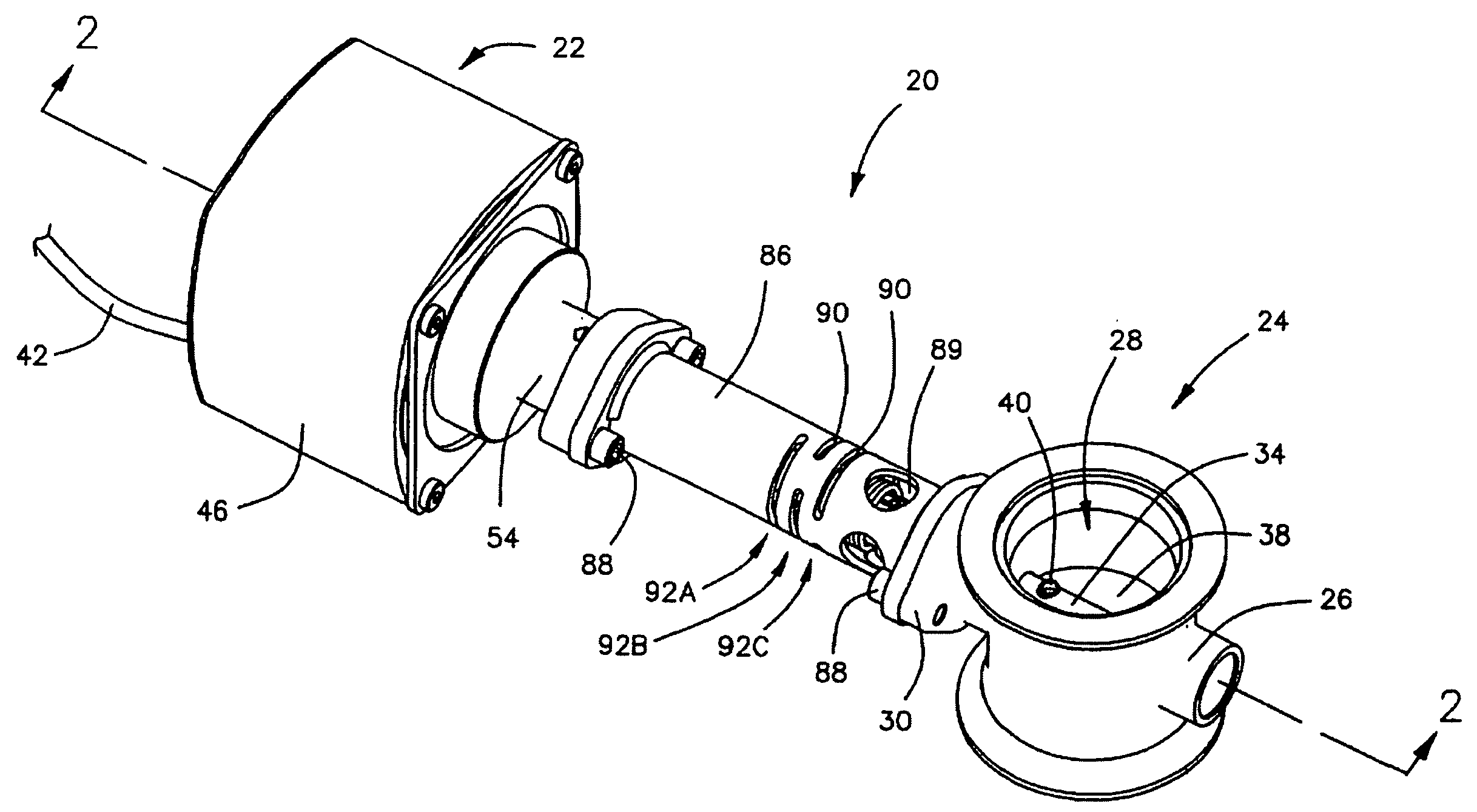
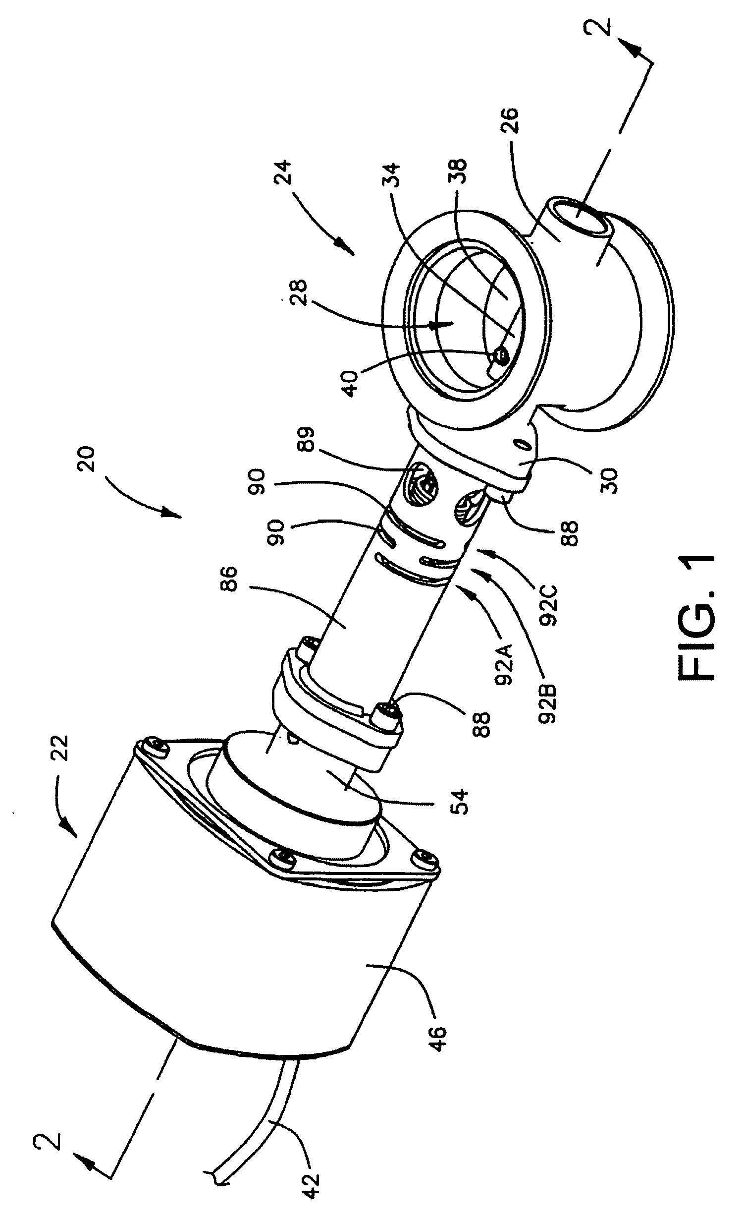
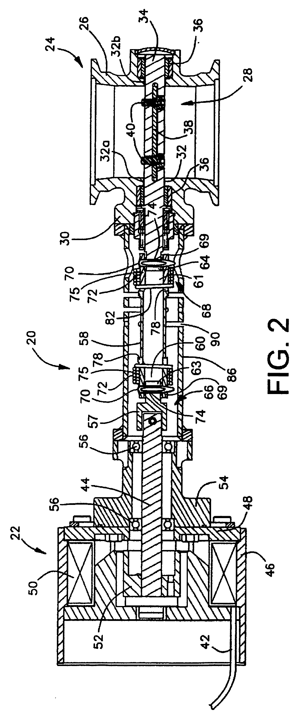
[0033]For purposes of illustration and referring to FIG. 1, a preferred embodiment of the present invention has been depicted as an electrically controlled butterfly valve apparatus 20 for high temperature applications. Although the preferred embodiment will be described as particularly adapted for controlling exhaust gas flow which may have a temperature of up to about 1400° F., it should be understood from the outset that the preferred embodiment may be adapted for controlling fluid flow in other high temperature engine applications and / or in association with other applications that need thermal isolation between a valve and an electrical actuator. These broader aspects are considered to be part of the present invention, and are covered by certain of the broader claims appended hereto.

[0034]To achieve better control of fluid flow in high temperature applications, the preferred embodiment of the present invention generally includes an electrical actuator 22 that has a continuously ...


PUM


Abstract

A coupling arrangement coupling and thermally isolating a continuously variable electrical actuator rotationally coupled to and from a butterfly valve is provided. The valve may be used to modulate high temperature exhaust gas flow through an engine turbocharger. The actuator provides a continuously variable control of the valve. The coupling arrangement provides a thermal block to reduce heat transfer and vibration insulation between the actuator and the valve. The coupling arrangement generally includes a coupling shaft rotationally coupled at opposite ends to the input and output shafts by torsion spring mechanisms. The torsion spring mechanisms include yokes rotationally locking the coupling shaft to the input and output shafts. The torsion spring mechanisms allow a limited range of axial and pivotal translation between the coupling shaft and the input and output shafts and are preloaded to prevent rotational hysteresis in the valve.

Description

FIELD OF THE INVENTION[0001]This invention relates generally to flow control valves and more particularly to continuously variable butterfly valves for applications in engines.BACKGROUND OF THE INVENTION[0002]There are a number of high temperature applications where fast and accurate control over fluid flow is needed. One exemplary and very significant application is controlling the boost pressure provided by a turbocharger. Turbochargers affect the air fuel (A / F) ratio combusted in the cylinders of modern internal combustion engines, which includes diesel and natural gas engines. Turbochargers include a compressor for compressing air and a turbine for driving the compressor. The turbine operates off of the exhaust flow exiting the engine. To achieve the most efficient engine performance, the boost pressure of the air delivered into the cylinders must be accurately controlled.[0003]One way to obtain better control over the compressor boost pressure is to control the amount of exhaus...

Claims


Application Information

Patent Timeline
Patent Type & Authority Applications(United States)
IPC IPC(8): F16H21/12
CPCF01N2260/20F02B37/183F02B39/00F02D9/04F02D9/1065Y10T74/1836F16D3/72F16D2300/02F16K1/221Y02T10/144F16D3/02Y02T10/12
Inventor PINTAURO, ARTHUR C.
Owner WOODWARD GOVERNOR CO
Why Eureka
Try Eureka