Pyrolysis apparatus

a technology of pyrolysis apparatus and pyrolysis chamber, which is applied in the direction of lighting and heating apparatus, combustible gas production, and combustion types, etc., can solve the problems of not only the damage to the environment, the waste of space, and the serious concern of solid waste materials, so as to relieve pressure

Inactive Publication Date: 2009-12-03
RAINBOW CONVERSION TECH
View PDF6 Cites 9 Cited by
  • Summary
  • Abstract
  • Description
  • Claims
  • Application Information

AI Technical Summary

Benefits of technology

[0005]Moreover, provision must be made for preventing corrosion and damage to the combustion equipment and instruments and to preventing pollution of the environment such as is caused by the gases resulting from the combustion of chlorinated organic materials.
[0024]Preferably, the receiving duct and input ducts are of square cross section and the thermal reactor is a round cross section of a larger diameter than the dimensions of the input duct. A transition between the square input duct and the round thermal reactor is provided which further enables free fall of the waste material introduced into the thermal reactor out by the feed mechanism.

Problems solved by technology

Disposal of solid waste materials is a serious concern.
Waste represents hazards to the environment in terms of not only the space it occupies but also the deleterious effects it has on the environment.
It has not been possible to treat all of these types of materials by ordinary combustion methods because offensive odors are generated as a result of imperfect combustion, the production of components which are extremely corrosive, particularly at high temperature, and the presence of substantial amounts of imperfectly combusted components in the residual ash.
Consequently, the difficulty in effecting complete combustion without harm to the environment has been such as to make the incineration operation uneconomical in most situations.
However, because of the very large volume of waste that is generated on a daily basis, particularly in high populated areas, acceptable landfill sites are rapidly reaching capacity and new sites have become difficult to find.
Many of these devices have proved unworkable or economically unfeasible.
Others, while feasible in concept have been proven to be inefficient and unreliable in continuous operation.
Still others, while attractive in theory, have been shown to be too expensive to manufacture, install and operate.
Several techniques have been employed to reduce the level of moisture in the waste before introducing it into the machine, because the presence of moisture makes the pyrolytic process less efficient.
Unfortunately, such conveyor devices are difficult to maintain.

Method used


Image

  • Pyrolysis apparatus
  • Pyrolysis apparatus
  • Pyrolysis apparatus

Examples


Embodiment Construction

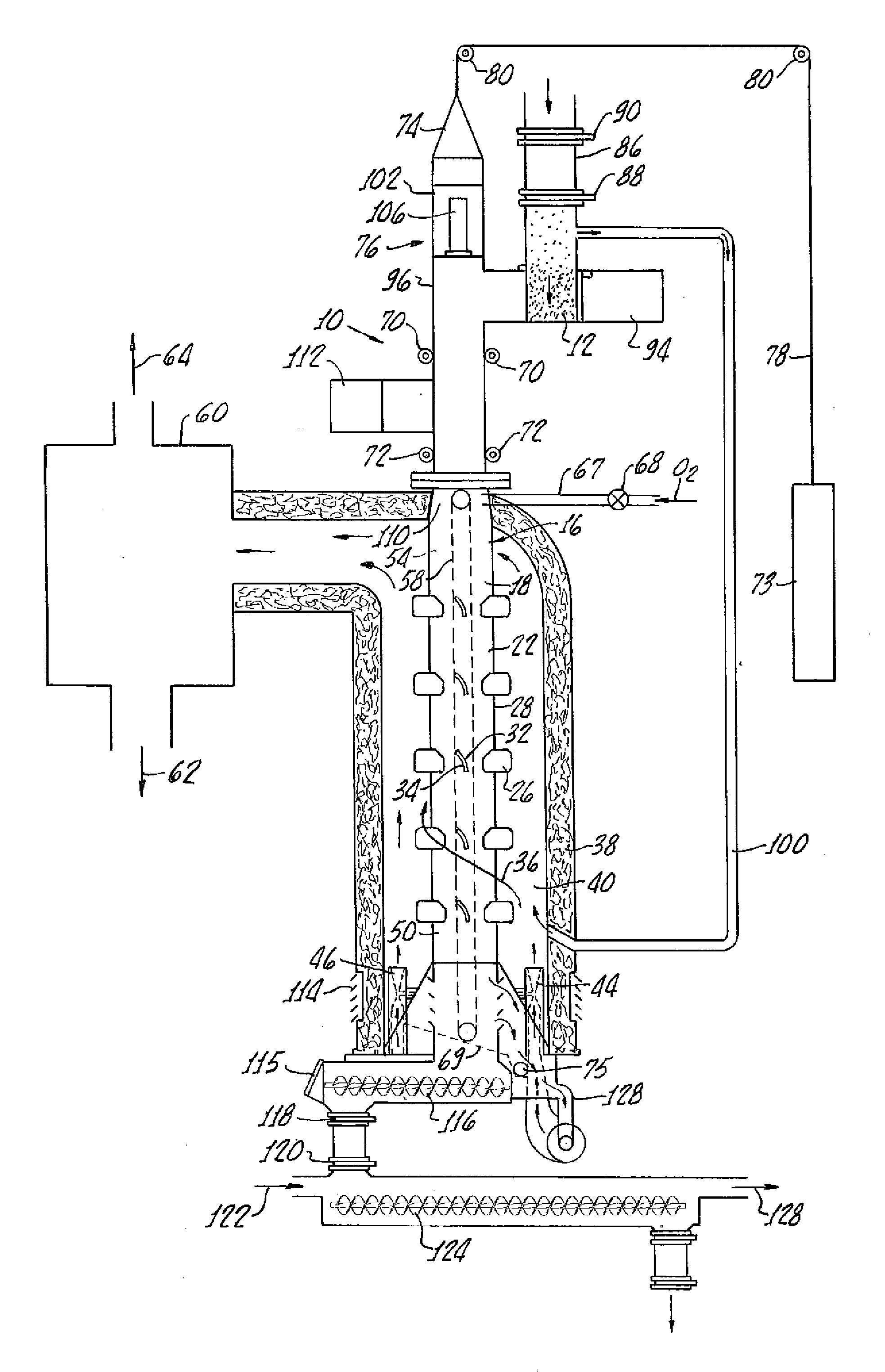
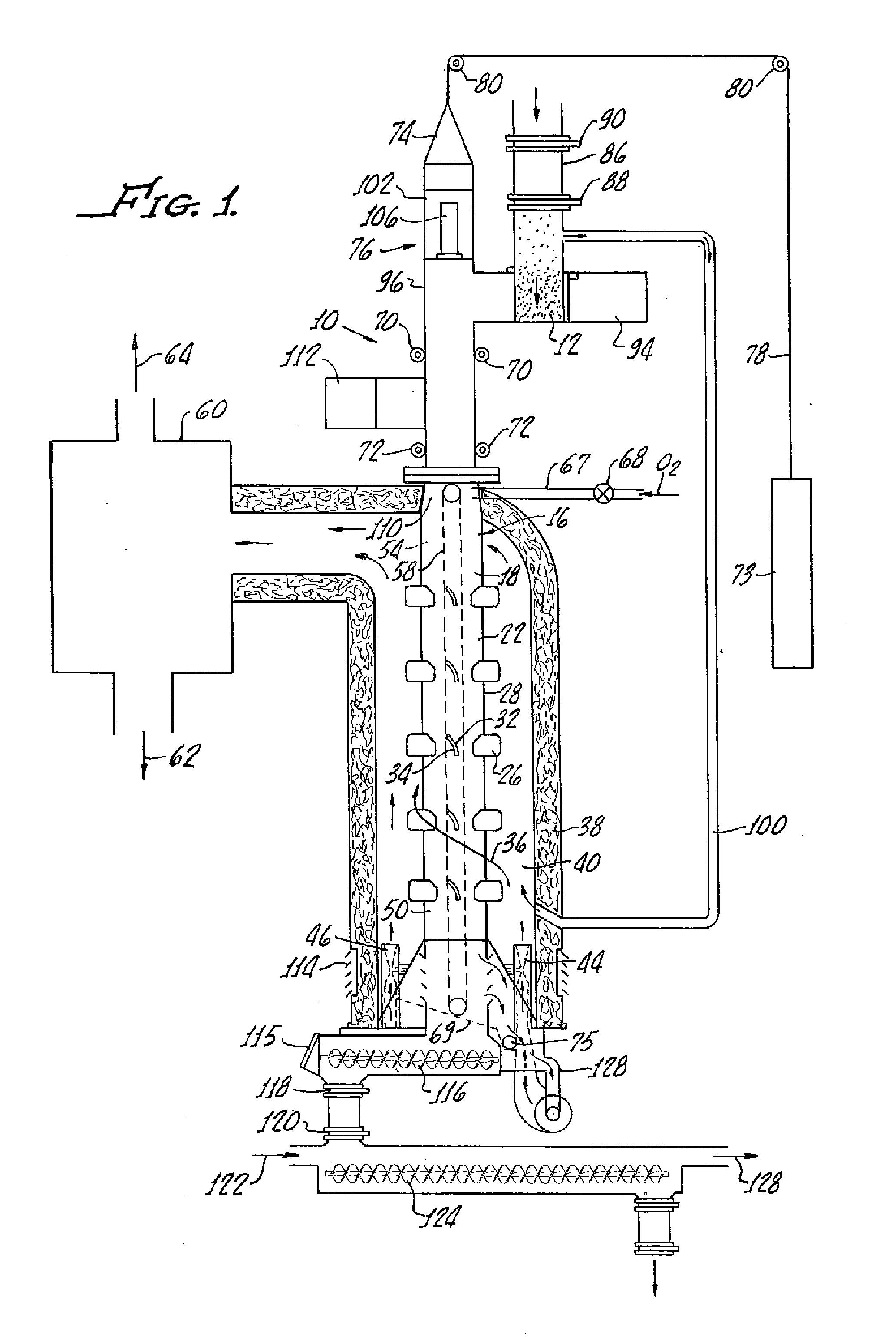
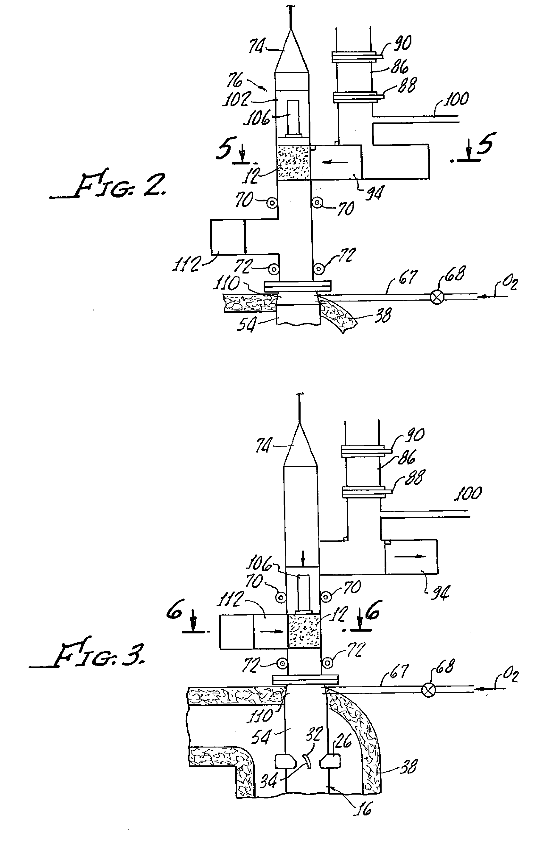
[0032]With reference to FIG. 1, there is shown apparatus 10 for the pyrolysis of solid waste material 12 which includes a thermal reactor 16 which includes elongate hollow housing 18 which defines a reaction chamber 22. As illustrated, the thermal reactor 16 is oriented in a manner, preferably vertically, in order to cause the solid waste material 12 fed thereinto to pass through the reaction chamber 22 by the force of gravity. Feeding of the waste material 12 into the thermal reactor 16 will be described hereinafter in greater detail.

[0033]A plurality of vanes 26 disposed transverse to the housing 18 and extend both exterior and interior to a housing wall 28 for both conducting heat into the reaction chamber 22 and for tumbling the waste material 12 as the waste material 12 passes through the reaction chamber 22. It should be appreciated that the materials of construction of the apparatus 10 are of a conventional nature typical to the material utilized in conventional pyrolysis app...


PUM


Abstract

Apparatus for the pyrolysis of solid waste material includes a thermal reactor including an elongate hollow housing with a reaction chamber disposed within the housing. The thermal reactor is vertically oriented in order to cause solid waste material fed thereinto to pass through said reaction chamber by the force of gravity and a plurality of vanes are disposed for both conducting heat into said reactor chamber and for tumbling said solid waste material as said solid waste material passes through said reaction chamber.

Description

[0001]The present invention generally relates to solid waste treatment systems and more particularly, the invention is directed to solid waste treatment systems in which waste is processed via a thermal reaction chamber.[0002]Disposal of solid waste materials is a serious concern. Waste represents hazards to the environment in terms of not only the space it occupies but also the deleterious effects it has on the environment. The increasing volume of waste and the dangerous conditions it may create has forced more attention to be paid to ways of dealing with the material.[0003]In general, solid waste materials from community and from various types of industrial facilities vary widely in composition, and may include, for instance, garbage, plastic scraps, tires, and other articles of rubber, scrap wood, oil-impregnated rags, and refuse oils, all of which are organic, as well as concrete debris and scrap metal. Consequently, it has been necessary to use a variety of types of disposal f...

Claims


Application Information

Patent Timeline
Patent Type & Authority Applications(United States)
IPC IPC(8): F23G5/28
CPCC10B47/20F23G2209/281C10J3/32C10J3/66C10J2200/154C10J2200/36F23G5/0276F23G5/28F23G5/444F23G2201/303F23G2203/80F23G2205/10F23G2205/16F23G2205/18F23G2207/30F23G2209/102F23G2209/28C10B53/00
Inventor SHUMAN, BRUCEMOFFATT, JERRYATWELL, BRUCEROMACLY, ROBERT J.ROMACLY, GLENN A.
Owner RAINBOW CONVERSION TECH
Why Eureka
Try Eureka