Ion trap array

a technology of ion traps and arrays, applied in the direction of isotope separation, electric discharge tubes, separation processes, etc., can solve the problems of destroying the mass resolution in the mass analysis procedure, the number of ions which may be stored in the 3-dimensional rotation symmetric ion trap is limited, and the linear ion trap cannot meet all needs, etc., to achieve the effect of simple geometry

Active Publication Date: 2009-12-03
FUDAN UNIV
View PDF21 Cites 64 Cited by
  • Summary
  • Abstract
  • Description
  • Claims
  • Application Information

AI Technical Summary

Benefits of technology

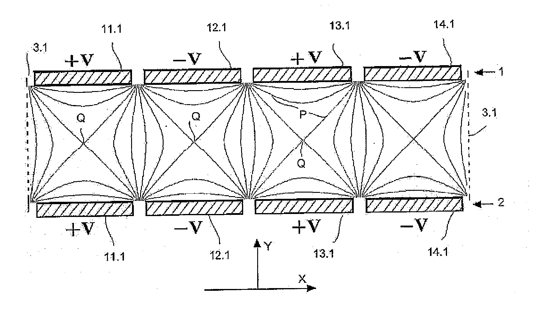
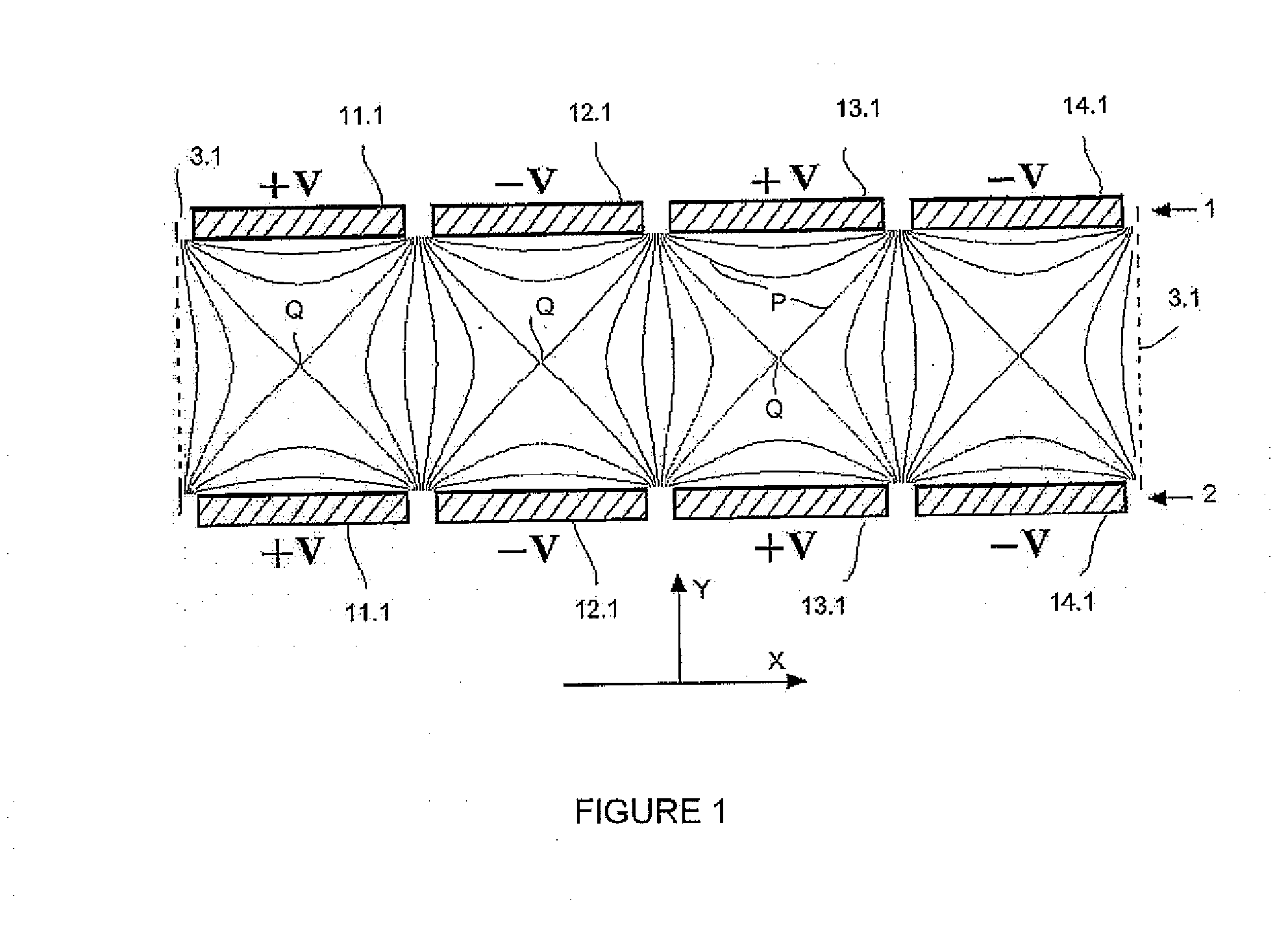
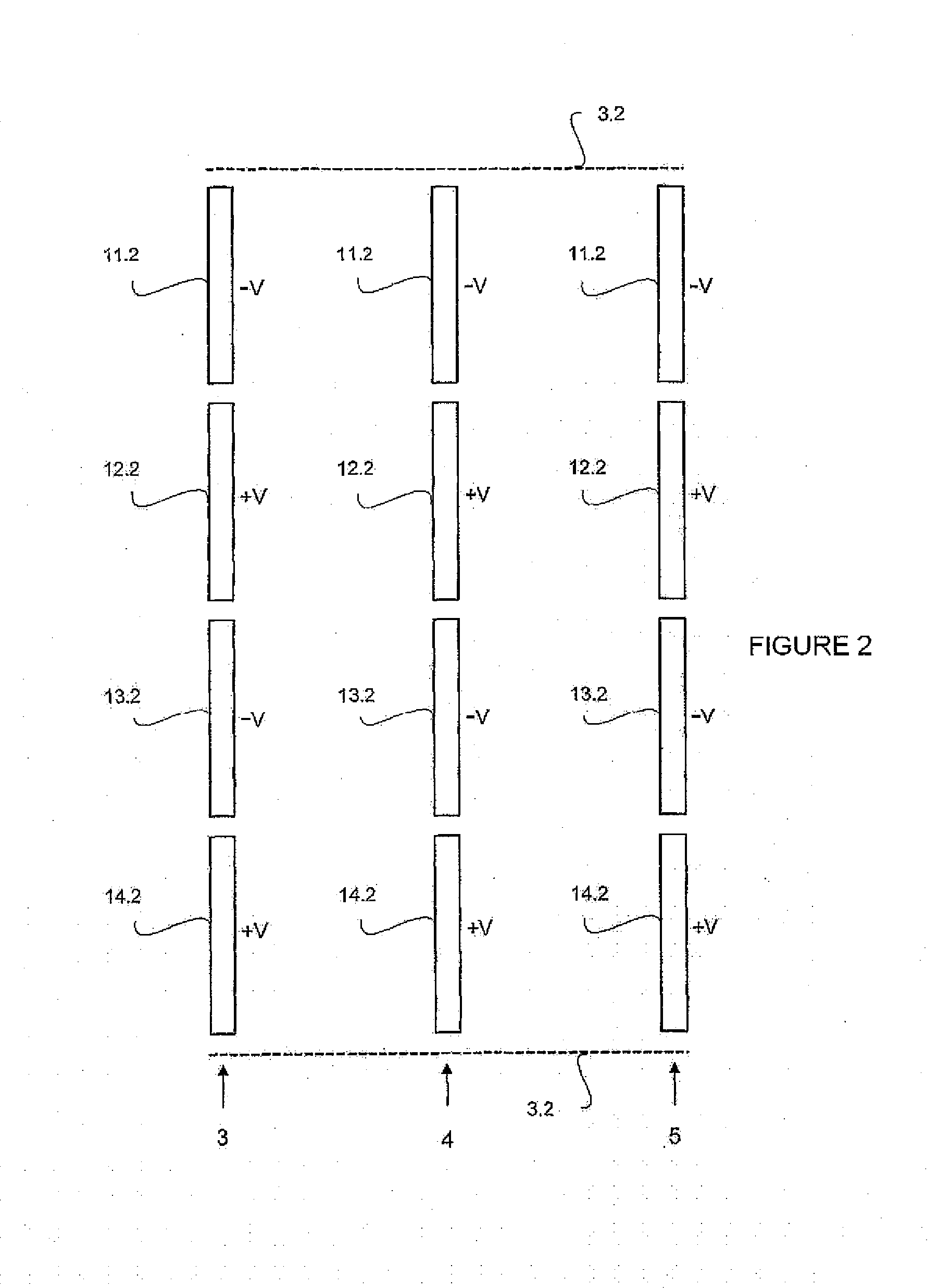
[0004]The aim of this invention is to provide a new ion trap array (ITA), with a simple geometry, to carry out parallel, multiplied axis ion storage. Ions st

Problems solved by technology

Due to the space-charge effect, the number of ions which may be stored in a 3-dimension rotation symmetric ion trap is limited.
Although a large number of ions can be successfully trapped inside a 3-dimension rotational symmetric ion trap, the severe charge-ch

Method used


Image

  • Ion trap array
  • Ion trap array
  • Ion trap array

Examples


case 1

Case 1:

[0061]FIG. 3 shows a method of the invention. The upper electrode array (1) and lower electrode array (2) both include seven rectangle electrode bars, namely, (1.3, 12.3, 13.3, 14.3, 15.3, 16.3, and 17.3). The electrode bars are made of metal plate, and have the same length in the Z direction, the length of each electrode bar is at least 3 times greater than the breadth of said electrode bar in the X direction (approximately tens of millimetres). The distance between the upper and lower electrode arrays is similar to the sum of the breadth of an electrode bar and the interval between two adjacent electrode bars, generally a few millimetres. The difference is less than 25%. Border electrodes (3.3 and 3.3a) are placed around the planar electrode arrays as the boundary of ion trap field. Electrode (3.3a) is placed on the boundary of paralleled electrode bars on Z direction and electrode (3.3) is placed next to the ends of electrode bars. Border electrodes have inlet holes, silts...

case 2

Case 2:

[0063]FIG. 4 shows another method in which ions are ejected and detected in the X direction. In FIG. 4, the detector (8.4) is placed outside the reticulate boundary electrode (3.4a). After trapped and mass-selected, ions are accelerated by an extractive pulse electric field which was produced by the resistor network (31, 32), and then pass through the boundary electrode (3.4a) on the right and hit the detector (8.4). Although in the FIG. 4 the resistor network (31, 32) are only connected to electrodes of the top electrode array, identical potential is applied to corresponding, opposite electrodes of the bottom electrode array. In cases where identical is potential applied on opposite electrodes, boundary electrodes can be manufactured as shown in FIG. 5: the ends of every electrode (11.5, 12.5, etc.) is joint directly with end plates to corresponding opposite electrodes (11.51, 12.51, etc.) without a zero-potential boundary electrode, and in such case, two electrodes on the o...


PUM


Abstract

The invention “Ion Trap Array (ITA)” pertains generally to the field of ion storage and analysis technologies, and particularly to the ion storing apparatus and mass spectrometry instruments which separate ions by its character such as mass-to-charge ratio. The aim of this invention is providing an apparatus for ion storage and analysis comprising at least two or more rows of parallel placed electrode array wherein each electrode array includes at least two or more parallel bar-shaped electrodes, by applying different phase of alternating current voltages on different bar electrodes to create alternating electric fields inside the space between two parallel electrodes of different rows of electrode arrays, multiple linear ion trapping fields paralleled constructed in the space between the different rows of electrode arrays which are open to adjacent each other without a real barrier. This invention also provides a method for ion storage and analysis involving with the trapping, cooling and mass-selected analyzing of ions by this apparatus mentioned which constructs multiple conjoint linear ion trapping fields in the space between the different rows of electrode arrays

Description

FIELD OF THE INVENTION[0001]This invention pertains generally to the field of ion storage and analysis technology and, particularly, to the ion storing components and mass spectrometry instruments which separate ions by characteristics such as mass-to-charge ratio, etc.BACKGROUND ART[0002]The family of alternating electric fields ion traps for ion storage and mass analysis includes 3-dimension rotational symmetric ion traps (3D-Rot. Sym.IT) and linear ion traps (LIT). In a 3-dimension rotational symmetric ion trap, ions are trapped around the center of the trap. Due to the space-charge effect, the number of ions which may be stored in a 3-dimension rotation symmetric ion trap is limited. Although a large number of ions can be successfully trapped inside a 3-dimension rotational symmetric ion trap, the severe charge-charge interaction between multiple ions will destroy the mass resolution in mass analysis procedure. In a linear trap, ions are stored around a middle axis of the trap. ...

Claims


Application Information

Patent Timeline
IPC IPC(8): B01D59/44H01J49/00
CPCH01J49/4235H01J49/004H01J49/4225H01J49/065
Inventor DING, CHUANFANDING, LI
Owner FUDAN UNIV
Why Eureka
Try Eureka