Voltage Divider, Constant Voltage Circuit Using Same, And Trimming Method In The Voltage Divider Circuit

Inactive Publication Date: 2009-12-03
RICOH ELECTRONIC DEVICES CO LTD
View PDF2 Cites 28 Cited by
  • Summary
  • Abstract
  • Description
  • Claims
  • Application Information

AI Technical Summary

Benefits of technology

[0028]Further, in a circuit that sets or determines voltage by varying resistance, a voltage drop by the resistance does not change. Accordingly, as long as the externally input voltage setting signal is the same, the output voltage or the detected voltage (the detection level of voltage) can be the same in a constant voltage circuit or a voltage detector circuit of any IC. Further, there is no need to perform voltage adjustment or t

Problems solved by technology

However, the adjusting circuit shown in FIG. 1 has a problem in that a finer unit of adjustment results in an increase in the number of adjusting resistors and fuses.
However, the number of adjusting resistors cannot be reduced, and in return for a decrease in the number of fuses, as many (256) switching elements as the conventional fuses and a decoder for performing on-off control on each switching element are required, thus causing a problem in that the circuit is extremely large in size.
However, this causes a problem in that the combined resistance of the adjusting circuit changes in accordance with the contents of trimming.
That is, since the voltage drop in each of the resistors Rs1 through Rs4 for output voltage changing varies, there is a problem in that inputting the same voltage setting signal does not result in the same output voltage Vout depending on the trimming result.
However, this requires the reference voltage generator circuit itself to be a constant voltage circuit with

Method used


Image

  • Voltage Divider, Constant Voltage Circuit Using Same, And Trimming Method In The Voltage Divider Circuit
  • Voltage Divider, Constant Voltage Circuit Using Same, And Trimming Method In The Voltage Divider Circuit
  • Voltage Divider, Constant Voltage Circuit Using Same, And Trimming Method In The Voltage Divider Circuit

Examples


Embodiment Construction

[0037]A description is given, with reference to the accompanying drawings, of an embodiment of the present invention.

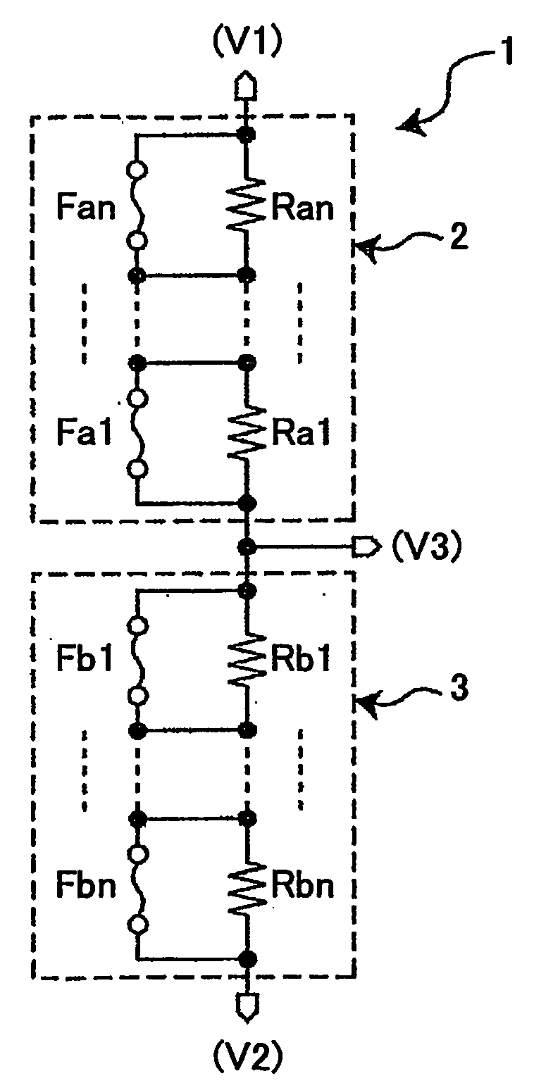
[0038]FIG. 4 is a diagram showing a voltage divider circuit 1 according to the embodiment of the present invention.

[0039]Referring to FIG. 4, the voltage divider circuit 1 includes a first resistor circuit 2 and a second resistor circuit 3 connected in series between a voltage V1 and a voltage V2. The voltage divider circuit 1 outputs a voltage V3 from the connection of the first resistor circuit 2 and the second resistor circuit 3.

[0040]Further, the first resistor circuit 2 includes adjusting resistors Ra1 through Ran and fuses Fa1 through Fan, and the second resistor circuit 3 includes adjusting resistors Rb1 through Rbn and fuses Fb1 through Fbn, where n is an integer greater than one (n>1). The first resistor circuit 2 and the second resistor circuit 3 have the same circuit configuration.

[0041]In the first resistor circuit 2, the adjusting resistors Ra1 through Ra...


PUM


Abstract

A voltage divider circuit generating a divided voltage by dividing an input voltage with a predetermined voltage division ratio, and outputting the divided voltage is disclosed. The voltage divider circuit includes a first resistor circuit including multiple resistors connected in series, the resistors being connected in parallel to corresponding fuses; and a second resistor circuit including multiple resistors connected in series, the resistors being connected in parallel to corresponding fuses, the second resistor circuit being connected in series to the first resistor circuit. The divided voltage is output from the connection of the first resistor circuit and the second resistor circuit, and the fuses of the first resistor circuit and the second resistor circuit are subjected to trimming so that the combined resistance of the first resistor circuit and the second resistor circuit is constant.

Description

TECHNICAL FIELD[0001]The present invention relates to a voltage divider circuit in a semiconductor device, a constant voltage circuit that uses the voltage divider circuit and is capable of varying output voltage, a voltage detector circuit that uses the voltage divider circuit and is capable of varying voltage to be detected, and a trimming method in the voltage divider circuit.BACKGROUND ART[0002]There are variations in the characteristics of various circuit elements formed on semiconductor integrated circuits because of variations in manufacturing processes. The variations in the characteristics of the circuit elements cause variations in the characteristics of entire circuits. If the circuit characteristics do not meet specifications, it is necessary to adjust the circuit characteristics by providing an adjuster circuit, for which adjustment resistor trimming is commonly employed.[0003]FIG. 1 is a diagram showing a circuit that adjusts the output voltage Vout of a constant volta...

Claims


Application Information

Patent Timeline
IPC IPC(8): H01H37/76
CPCG05F1/56G05F3/16
Inventor ITOH, KOHZOH
Owner RICOH ELECTRONIC DEVICES CO LTD
Why Eureka
Try Eureka