Check patentability & draft patents in minutes with Patsnap Eureka AI!

SCR circuit for protecting customer end of telephone line

Inactive Publication Date: 2009-12-03
LITTELFUSE INC
View PDF23 Cites 5 Cited by
  • Summary
  • Abstract
  • Description
  • Claims
  • Application Information

AI Technical Summary

Benefits of technology

[0011]In accordance with the principles and concepts of the invention, there is disclosed a protection circuit employing SCR devices cross coupled between a pair of conductors to provide overvoltage and overcurrent protection to such conductors. When used in conjunction with telephone line conductors, the unidirectional conducting feature of the SCR devices prevents the central office SLIC circuits from sourcing current in response to a negative overvoltage on the telephone line.

Problems solved by technology

Telephone lines, like other types of electrical conductors, are subject to electrical interference which can damage circuits connected to such conductors.
By necessity, telephone lines are located outside buildings and are subject to lightning strikes, AC power line crosses and other electrical interferences.
The electrical energy coupled to a telephone line, whether it be a lightning strike or an AC power line cross, is substantial and can be sufficient to damage electrical circuits connected to the lines unless such lines are provided with protection.
While this might facilitate the sensing and shunting of overvoltages and overcurrents on the telephone line, the nonlinear characteristics of such devices, especially if the communication signals must pass through semiconductor junctions, is highly undesirable.
The interposition of semiconductor junctions in series with a telephone line conductor presents a nonlinear condition to signals of different amplitudes, and thus may deteriorate the telephone line characteristics initially relied upon by the designers.
Some systems use voltages with positive excursions during ringing conditions, but many even restrict ringing signals to negative voltages.
This assumption may often be erroneous, thus allowing abnormal operation without activating the protection devices.

Method used


Image

  • SCR circuit for protecting customer end of telephone line
  • SCR circuit for protecting customer end of telephone line
  • SCR circuit for protecting customer end of telephone line

Examples


Embodiment Construction

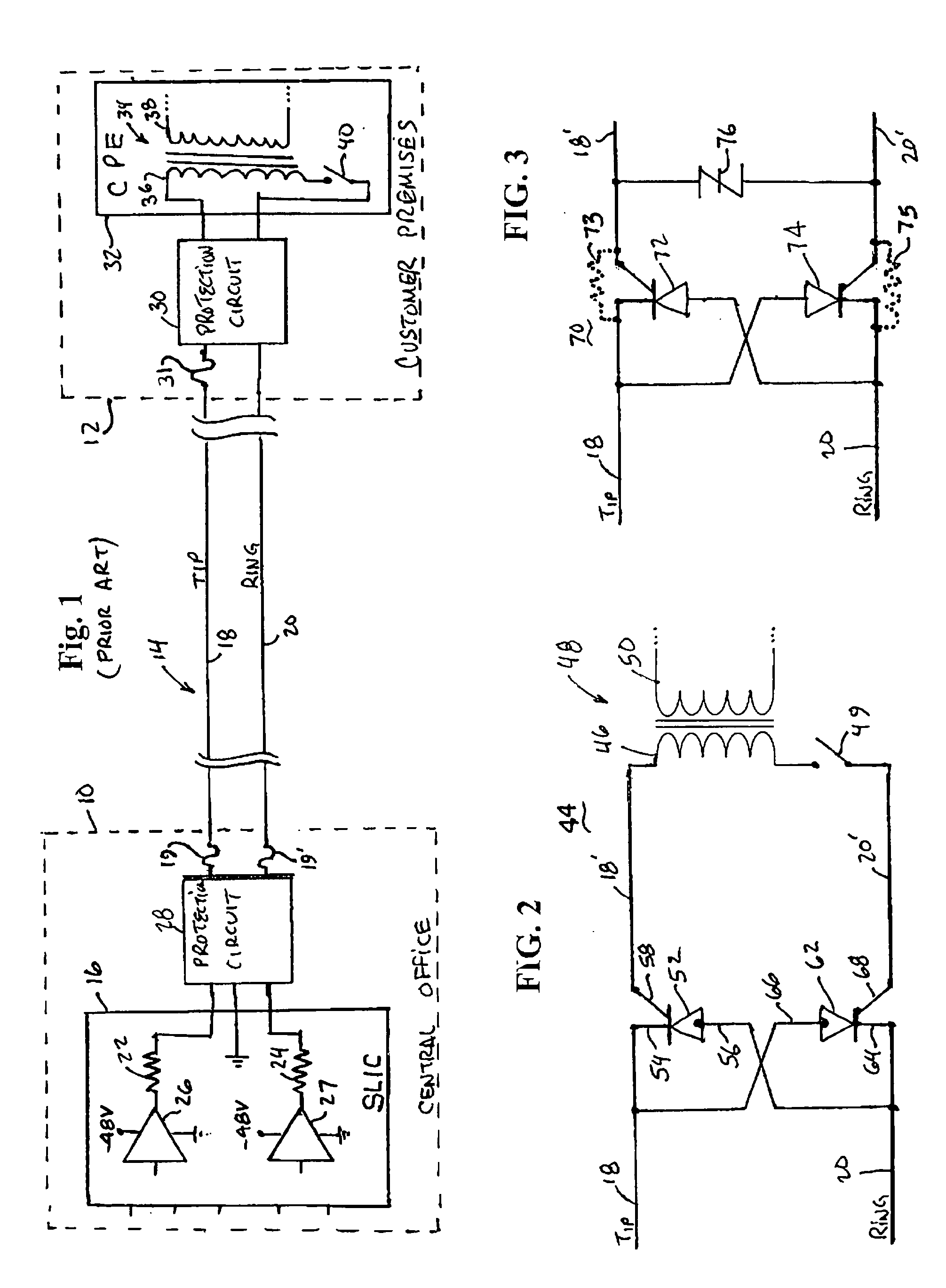
[0033]With reference to FIG. 1, there is shown a diagram of the termination of a standard telephone line 14 at both the central office 10 and the customer premises 12. The telephone central office 10 includes a subscriber line interface circuit (SLIC) 16, shown in much simplified form, that provides an interface between the telephone line 14 and the other switching equipment (not shown) of the central office 10. There is generally one SLIC 16 for each twisted pair telephone line 14. The telephone line 14 includes a tip conductor 18 and a ring conductor 20. In practice, the SLIC 16 includes a pair of feed resistors 22 and 24, nominally of about 100-200 ohm, to provide protection to the SLIC circuits 16 if the tip conductor 18 and the ring conductor 20 become short circuited together. The office battery is nominally of a voltage of about −48 volts, and ranges between about 50-52 volts. The SLIC 16 may include many other circuits, including a 2 w / 4 w hybrid circuit, line current sensin...


PUM


Abstract

A protection circuit employing a pair of SCR devices cross coupled between a telephone line tip conductor and ring conductor. The SCR devices are of the type providing internal semiconductor resistors between the gate and cathode terminals for sensing overcurrents in the telephone line conductors, and providing voltage sensitive semiconductor regions so that the SCR devices are sensitive to overvoltages on the telephone line conductors. When employed with a telephone line termination transformer, the internal resistor of one SCR device provides the series resistance, together with the transformer winding resistance, for reliably allowing the other SCR device to be triggered into conduction and remain in a latched condition in response to an overcurrent condition.

Description

RELATED APPLICATION[0001]This non-provisional patent application relates to U.S. non-provisional patent application entitled “SCR Circuit For Protecting Central Office End Of Telephone Line,” filed even date herewith, and identified by attorney docket number TCCR-2300US.TECHNICAL FIELD OF THE INVENTION[0002]The present invention relates in general to telephone line protection circuits and techniques, and more particularly to such type of circuits employing gated unidirectional thyristor devices.BACKGROUND OF THE INVENTION[0003]Telephone lines, like other types of electrical conductors, are subject to electrical interference which can damage circuits connected to such conductors. By necessity, telephone lines are located outside buildings and are subject to lightning strikes, AC power line crosses and other electrical interferences. The electrical energy coupled to a telephone line, whether it be a lightning strike or an AC power line cross, is substantial and can be sufficient to da...

Claims


Application Information

Patent Timeline
IPC IPC(8): H02H9/04
CPCH04M1/745H01L27/0248
Inventor CASEY, KELLY C.
Owner LITTELFUSE INC
Features
  • R&D
  • Intellectual Property
  • Life Sciences
  • Materials
  • Tech Scout
  • Unparalleled Data Quality
  • Higher Quality Content
  • 60% Fewer Hallucinations
Learn More