

Method for Simulating a Controller and/or Machine Response of a Machine Tool or of a Production Machine
- Summary
- Abstract
- Description
- Claims
- Application Information
AI Technical Summary
Benefits of technology
Problems solved by technology
Method used
Image

Examples
Embodiment Construction
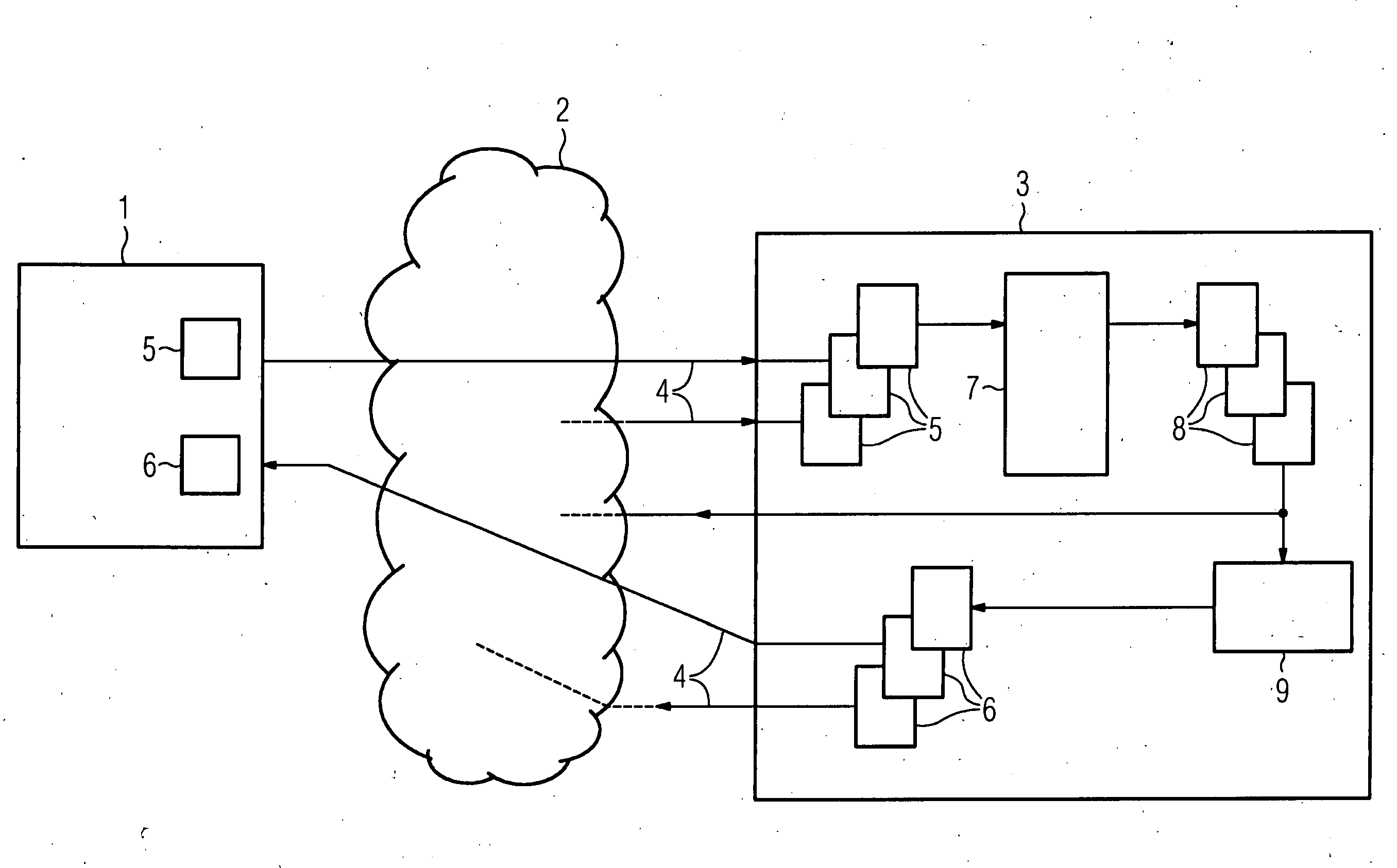
[0058]The illustration according to FIG. 1 shows a symbolic diagram of a machine 1. The machine 1 is a machine tool for example, which has a CNC (Computer Numerical Control), or a production machine. Data 5 is stored in the machine 1. This data 5 can be transmitted by way of an internet 2 by means of a data transfer 4 to a simulation facility 3, with the data relating for example to configuration data, wear data and / or traces. The simulation facility 3 is for example also a system for monitoring manufacturing and / or production planning. The simulation facility 3 is provided in particular as a controller emulation and / or as a facility for executing other simulation models (e.g. simulation with a CNC emulation), with persistent storage of model process data being carried out for example in the simulation facility 3.
[0059]A number of different data items 5 from one or more machines (not shown) are stored on the simulation facility 3. The data 5 is used for a simulation 7 on the simulat...
PUM
 Abstract
Description
Claims
Application Information