Three-Way Ratchet Drive Mechanism

a ratchet drive and three-way technology, applied in the direction of friction clutches, automatic clutches, freewheel clutches, etc., can solve the problems of inconvenient switching between clockwise and anti-clockwise ratcheting operation modes, affecting the operation of objects, and affecting the effect of ratcheting operation

Inactive Publication Date: 2009-12-10
WINSIRE ENTERPRISES CORP
View PDF19 Cites 3 Cited by
  • Summary
  • Abstract
  • Description
  • Claims
  • Application Information

AI Technical Summary

Benefits of technology

[0023]To further advantage, particularly to enable ease of rotation of the drive shaft, the foregoing ratchet drive mechanism may include a shaft bearing abutting the proximal end of the drive shaft.
[0024]To still further advantage, the drive shaft may have a radially stepped cylindrical configuration, the first ...

Problems solved by technology

However, disadvantageously, many of such tools typically have no third or non-ratcheting mode of operation or setting where ratcheting behaviour can be locked out/disabled and the drive mechanism of the tool engages whether the tool is turned clockwise or anti-clockwise.
In this situation, it can be quite inconvenient to have to switch back and forth between clockwise and anti-clockwise modes of ratcheting operation.
It appears to be suggested that this object is compromised by conventional drive mechanisms where pawls extend in the axial direction of a shaft.
But, the alternative mechanism...

Method used


Image

  • Three-Way Ratchet Drive Mechanism
  • Three-Way Ratchet Drive Mechanism
  • Three-Way Ratchet Drive Mechanism

Examples


first embodiment

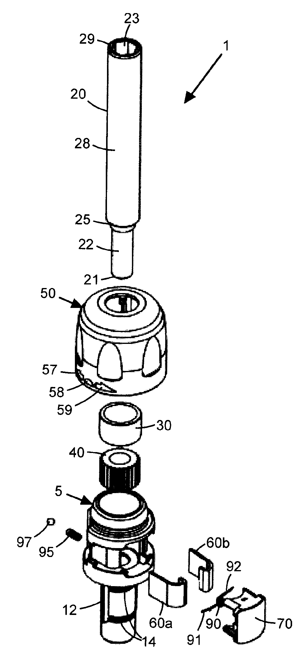
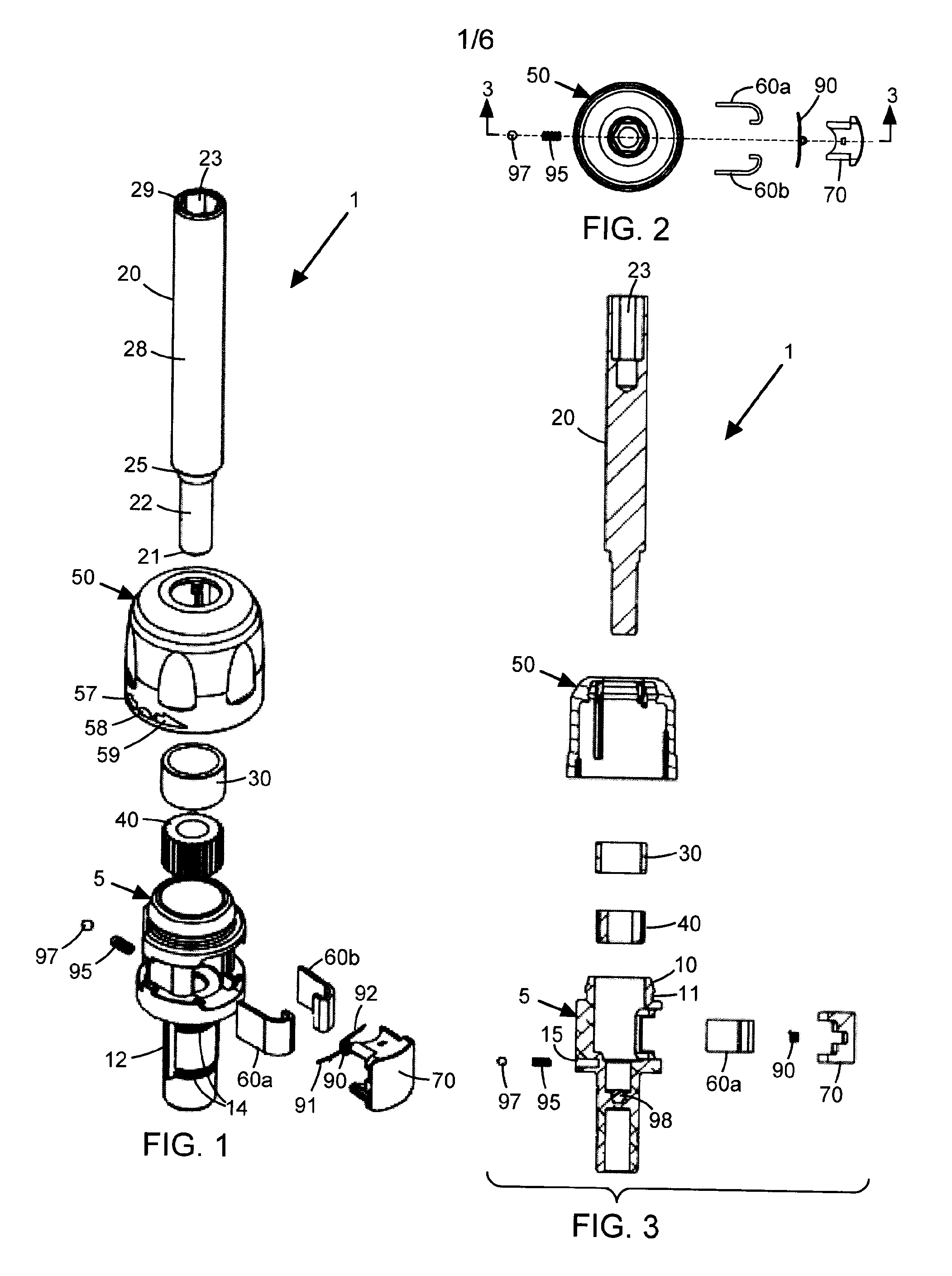
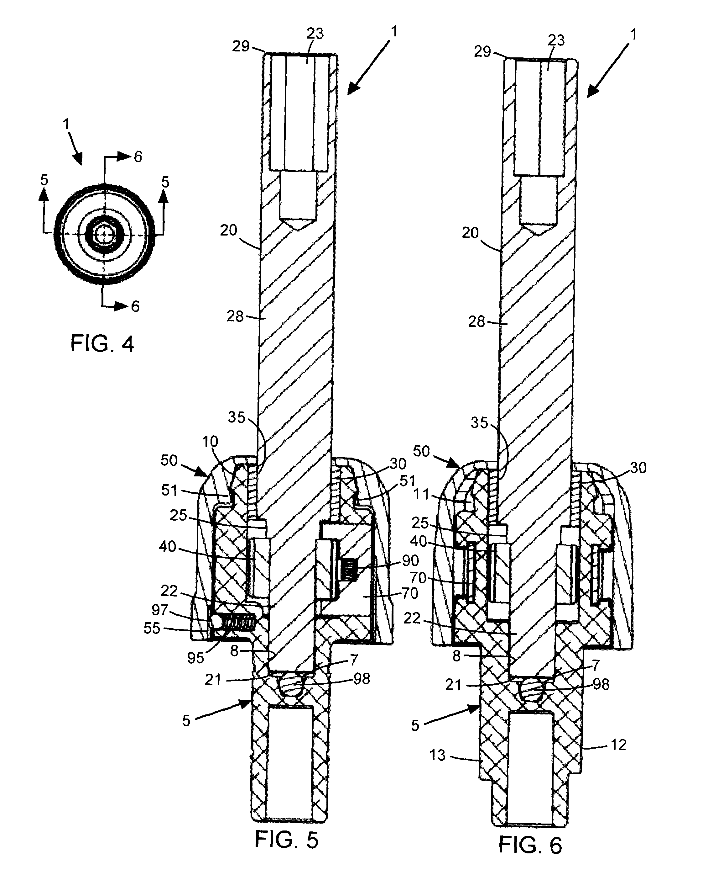
[0061]Referring now to FIGS. 1-12, there is shown a ratchet drive mechanism generally designated 1 for a work tool such as a screwdriver bit (not shown). Drive mechanism 1 includes a die cast aluminum ratchet housing generally designated 5, a generally cylindrical steel drive shaft 20 extending from a relatively small diameter proximal end 21 of end portion 22 of the shaft to a relatively large diameter distal end 29 of end portion 28 of the shaft, an annular plastic bearing sleeve 30 fitted to the housing, a steel spline or ratchet wheel 40 which is coaxially press fitted on end portion 22 of shaft 20, a resilient plastic selector sleeve generally designated 50, a pair of J-shaped steel ratchet pawls 60a, 60b which are of substantially the same size, and a plastic retaining clip 70. As well, drive mechanism 1 includes an inner steel coil spring 90, a steel selector spring 95, a steel selector ball 97, and a steel shaft bearing 98, the latter of which is a seated in a recess 7 forme...

second embodiment

[0071]In a second embodiment of the present invention, it is contemplated that the means used to perform the function of coil spring 90 in the first embodiment advantageously can also be used to perform the function of selector spring 95 and selector ball 97 in the first embodiment. The result is fewer parts since the need for the selector spring and selector ball is avoided.

[0072]In more detail and referring now to FIGS. 19-23, there is shown a ratchet drive mechanism generally designated 200 which is substantially the same as ratchet drive mechanism 1 but for the following differences:[0073](1) a plastic retaining clip 270 is used instead of retaining clip 70;[0074](2) a steel dual action coil spring 290 with arms 291, 292 as best seen in FIGS. 24-25 is used instead of coil spring 90;[0075](3) there is no selector spring or selector ball.

[0076]Retaining clip 270 holds spring 290 in a position where its arms 291, 292 bear against pawls 60a, 60b thereby urging the pawls substantiall...


PUM


Abstract

A compact, three-way ratchet drive mechanism selectively enables ratcheting operation in a clockwise direction, or an anti-clockwise direction, or disables ratcheting behaviour. The mechanism includes a ratchet housing, a drive shaft, a ratchet wheel, J-shaped pawls, and a coaxially fitted selector sleeve for selecting a desired mode of operation.

Description

CROSS-REFERENCE TO RELATED APPLICATIONS[0001]This application is related to U.S. provisional application No. 60 / 774,627 filed Feb. 21, 2006, entitled “Three-Way Ratchet Tool Mechanism”, naming Waltherus Christianus Klomp as the inventor. The contents of the provisional application are incorporated herein by reference in their entirety, and the benefit of the filing date of the provisional application is hereby claimed for all purposes that are legally served by such claim for the benefit of the filing date.BACKGROUND OF THE INVENTION[0002]The present invention relates to a ratchet drive mechanism for a screwdriver bit or other work tool.[0003]There are a wide variety of known designs for ratchet tools. Typically, such tools have two modes of operation, either one of which may be selectively set by the user. In the first mode (for example to tighten a screw) ratcheting operation is enabled in a clockwise direction. In the second mode (for example to loosen a screw) ratcheting operati...

Claims


Application Information

Patent Timeline
IPC IPC(8): B25B13/46F16D41/16
CPCB25B13/463F16D41/16B25B15/04B25B13/468
Inventor KLOMP, WALTHERUS CHRISTIANUS
Owner WINSIRE ENTERPRISES CORP
Why Eureka
Try Eureka