Engine cooling system

a cooling system and engine technology, applied in the direction of engine cooling apparatus, control devices of cooling apparatus, machines/engines, etc., can solve the problems of large pressure drop across the radiator than the current design can withstand, internal erosion inside the radiator core, and give a very slight increase in heat rejection, so as to increase the cooling capacity of the cooling system, high engine speed, and high coolant flow

Inactive Publication Date: 2009-12-10
VOLVO LASTVAGNAR AB
View PDF7 Cites 23 Cited by
  • Summary
  • Abstract
  • Description
  • Claims
  • Application Information

AI Technical Summary

Benefits of technology

[0001]The invention relates to an engine cooling system provided with means for controlling the pressure in different sections of the cooling system during different engine operating modes. This allows one section to be pressurized during a cold start to avoid cavitation, while another circuit can be protected from excessive pressure when the engine is operated at high speed.
[0008]In order to protect the radiator from excessive pressures, a pressure sensitive by-pass valve can be installed. This will limit the pressure drop over the radiator to an acceptable level and direct at least a part of the coolant flow into a by-pass conduit connected between the valve and a conduit downstream of the radiator. However, the use of this type of valve will require a relatively long time for pressurizing the cooling system during a cold start.
[0015]The controller may also control the first and second controllable valves in response to the input from a temperature sensor that is preferably, but not necessarily, located in the coolant circuit immediately downstream of the pump. The temperature sensor may alternatively be located in a suitable location between the radiator and the pump. If relatively cold coolant from the initially closed circuit containing the radiator enters parts of the coolant circuit containing the engine block with its cylinder liners, an optional EGR-cooler and similar relatively hot components, then the hot components may experience a thermal shock. If the temperature sensor downstream of the pump senses that the coolant from the radiator is below a predetermined limit, then the flow trough the first valve will be reduced and the flow through the second valve will be increased a corresponding amount. This control of the first valve also prevents relatively hot coolant from the engine from causing a thermal shock in the part of the cooling system containing the relatively cold radiator. The temperature is monitored until the radiator has reached a nominal operating temperature.
[0016]In this way components such as cylinder liners, EGR-coolers and similar will by supplied with coolant at a relatively high pressure (system pressure plus pump pressure) immediately after start. This prevents a local build-up of heat from causing cavitation adjacent the cylinder liners in the engine block and other parts of the pressurized coolant conduits of the engine.
[0017]During a second mode of operation the first and second controllable valves are controlled simultaneously or substantially simultaneously, wherein the total flow through the valves is equal to or substantially equals the flow delivered by the pump. The second mode of operation is used in order to control the pressure in the section of the coolant circuit that passes through the radiator. During periods where the engine is operated under a high load and / or a high engine speeds it is desirable to increase the cooling capacity of the cooling system. The coolant flow and pressure delivered by a fixed displacement pump driven by the engine is dependent on the engine speed. Hence a relatively high engine speed will result in a relatively high coolant flow and an increased system pressure.
[0018]Alternatively an increase in the coolant flow may be achieved by increasing the speed of an electrically driven pump or controlling a variable displacement pump, which increases both the coolant flow and the pressure in the cooling system.

Problems solved by technology

Increasing the flow of coolant may, however, cause a number of problems.
An increase of the coolant flow through a radiator may result in a larger pressure drop across the radiator than the current design can withstand.
The coolant flow may become high enough to cause internal erosion inside the radiator core.
Hence, an additional increase in coolant flow may only give a very slight increase in heat rejection.
Additional problems relating to cooling of vehicle engines involves the risk of cavitation in the engine block and the failure of engine heat exchangers such as EGR-coolers due to the effect of the coolant boiling in local hot-spots.
The maximum pressure that can be used in the cooling system is limited by the design pressure of the radiator.
One problem with an engine cooling system of this type is that the increased system pressure adds to the pressure drop over radiator.
The total pressure drop may therefore become too high for the radiator resulting in coolant leaks or even burst coolant conduits or tubes.
Hence, a local build-up of heat in the engine may cause cavitation to occur in coolant conduits in the engine during a cold start before the cooling system pressure builds up.
However, this solution will not solve the problem relating to a large pressure drop over the radiator.
However, the use of this type of valve will require a relatively long time for pressurizing the cooling system during a cold start.
If relatively cold coolant from the initially closed circuit containing the radiator enters parts of the coolant circuit containing the engine block with its cylinder liners, an optional EGR-cooler and similar relatively hot components, then the hot components may experience a thermal shock.
Hence a relatively high engine speed will result in a relatively high coolant flow and an increased system pressure.

Method used


Image

  • Engine cooling system
  • Engine cooling system
  • Engine cooling system

Examples


Embodiment Construction

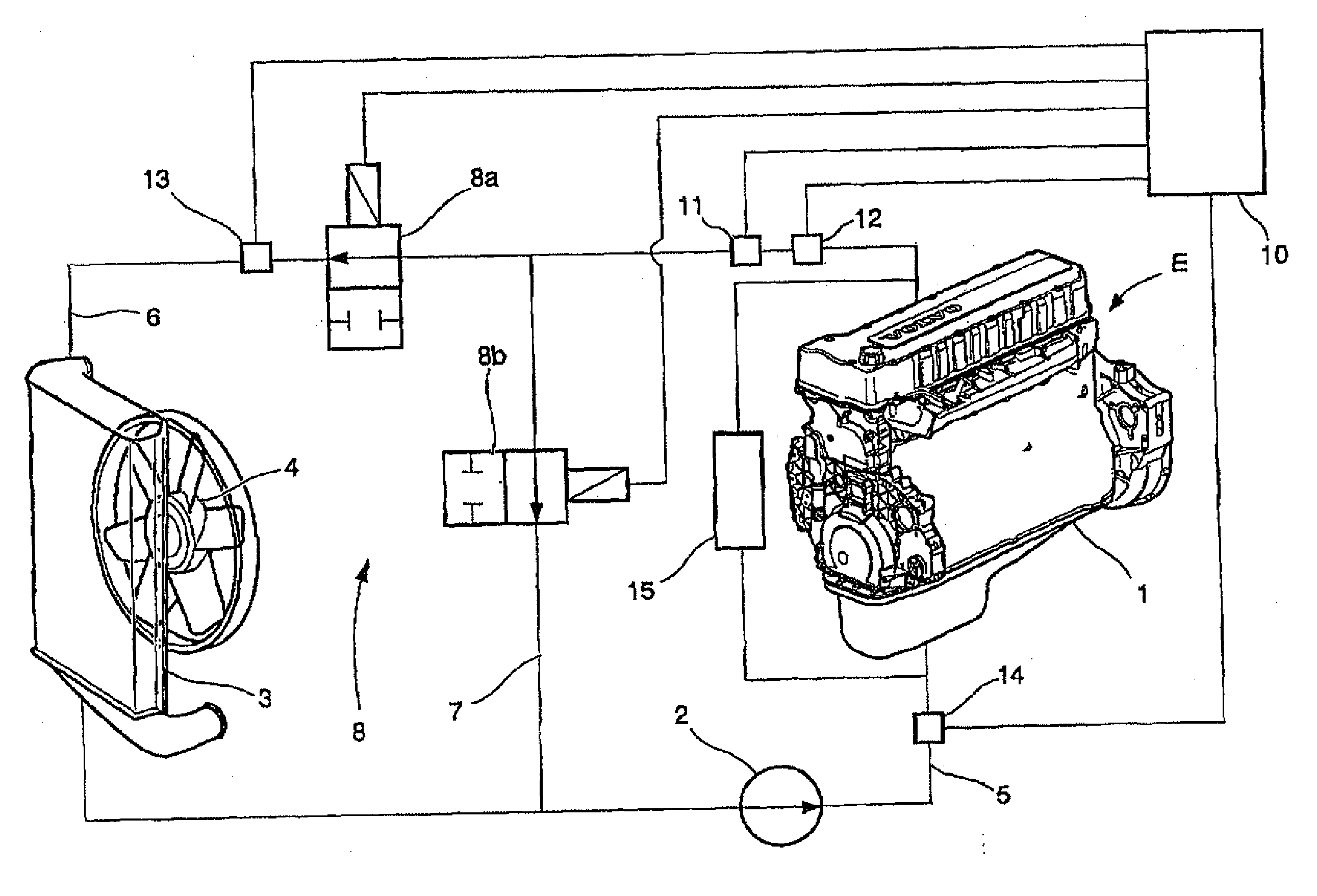
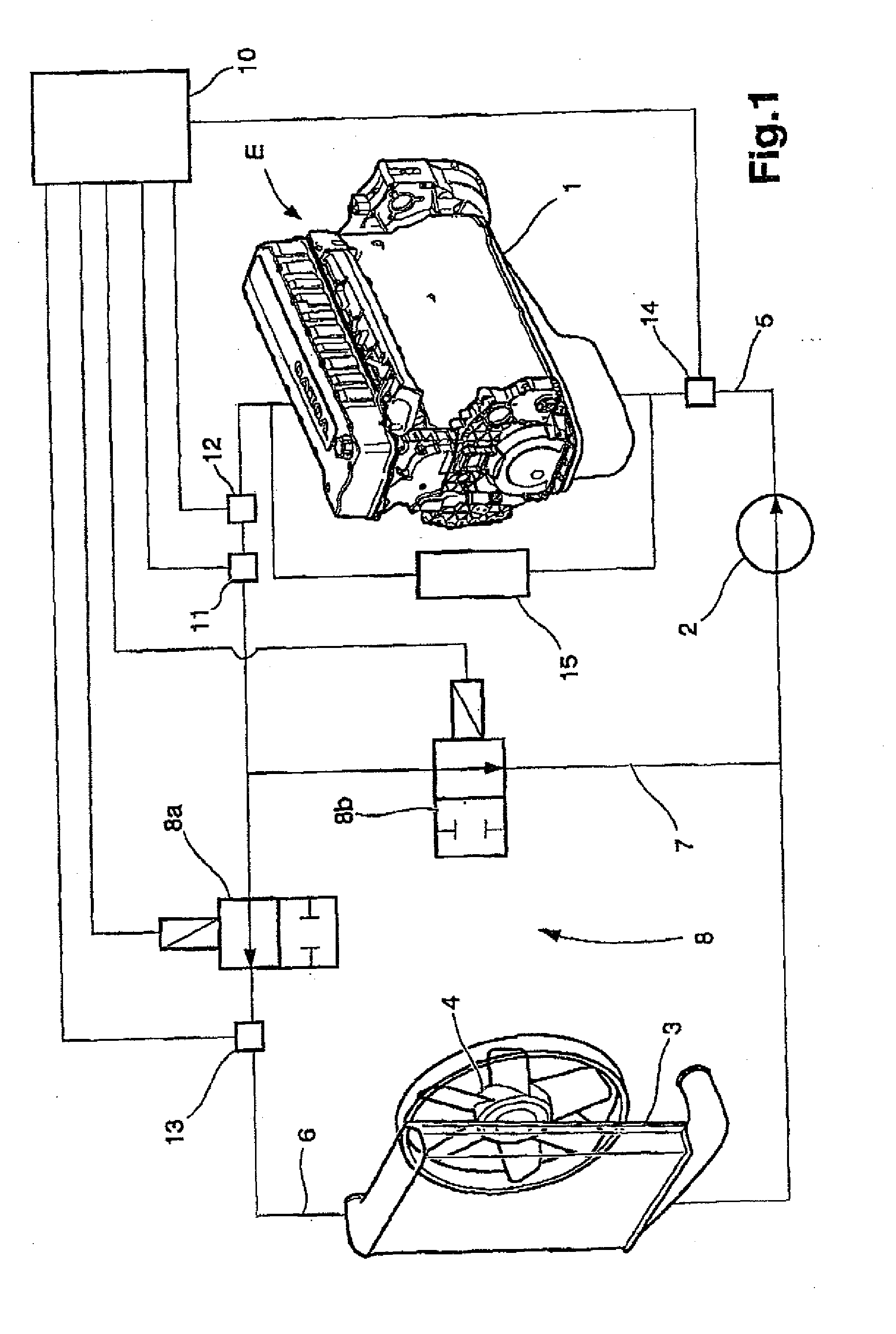
[0023]FIG. 1 describes an engine cooling system comprising a coolant circuit extending through an engine block 1 of an engine E, wherein a coolant such as water flows through the coolant circuit. A centrifugal pump 2 is provided for circulating coolant under pressure through the coolant circuit and a radiator 3 is provided for cooling coolant passing through the coolant circuit. A driven fan 4 is mounted adjacent the radiator 3 to control the flow of ambient air through the radiator. The coolant circuit further comprises a first section 5 comprising the engine block 1 and the pump 2 and a second section 6 comprising the radiator 3. The coolant circuit further comprises a by-pass conduit 7, wherein the by-pass conduit 4 allows coolant to by-pass the radiator 3.

[0024]A flow control valve means 8 is arranged for regulating the flow rate of coolant flowing through the radiator 3 and the by-pass conduit 7, respectively. The flow control valve means 8 comprises a first controllable valve ...


PUM


Abstract

An engine cooling system in which a coolant flows through a coolant circuit includes: a pump for circulating coolant under pressure through the coolant circuit; a radiator provided in the coolant circuit, wherein the radiator cools coolant passing through the coolant circuit; a by-pass conduit, wherein the by-pass conduit allows coolant to by-pass the radiator, a flow control valve, which regulates the flow rate of coolant flowing through the radiator and the by-pass conduit; and a controller, wherein the controller controls the flow control valve in response to input signals from at least one pressure sensor and at least one temperature sensor in the coolant circuit. The flow control valve includes a first controllable valve located upstream of the radiator and downstream of the by-pass conduit, and a second controllable valve located in the by-pass conduit.

Description

BACKGROUND AND SUMMARY[0001]The invention relates to an engine cooling system provided with means for controlling the pressure in different sections of the cooling system during different engine operating modes. This allows one section to be pressurized during a cold start to avoid cavitation, while another circuit can be protected from excessive pressure when the engine is operated at high speed.[0002]Due to a number of factors, such as stricter emission standards and more accessories requiring cooling, the demand for cooling of engine components and accessories is continuously increasing. Consequently, future vehicle engines, in particular truck engines, will require a higher coolant flow compared to current production engines to cope with the increased demand. Increasing the flow of coolant may, however, cause a number of problems.[0003]An increase of the coolant flow through a radiator may result in a larger pressure drop across the radiator than the current design can withstand...

Claims


Application Information

Patent Timeline
Patent Type & Authority Applications(United States)
IPC IPC(8): F01P7/14
CPCF01P7/167F01P2037/02F01P2007/146
Inventor DAHL, ERIKADELMAN, STEVEN
Owner VOLVO LASTVAGNAR AB
Why Eureka
Try Eureka