Liquid Tank Connector

a technology for liquid tanks and connectors, applied in the direction of hose connections, couplings, liquid transferring devices, etc., to achieve the effect of preventing contents from leakage, improving operability, and preventing leakage of contents

Active Publication Date: 2009-12-10
SURPASS IND
View PDF6 Cites 5 Cited by
  • Summary
  • Abstract
  • Description
  • Claims
  • Application Information

AI Technical Summary

Benefits of technology

[0016]Since the cock is adapted to be positioned at the gas flow channel forming position and the exhaust channel forming position, the liquid deliverable state and the separable state are reliably realized.
[0017]The liquid tank connector in the present invention described above achieves the following specific advantages. Since the socket is prevented from being removed in the liquid deliverable state and also in the state in which the interior of the liquid tank is pressurized by controlling the relative movement of the sleeve by the position of the cock in the liquid deliverable state, leakage of the contents is prevented.
[0018]Also, since the exhaust channel for exhausting the gas in the liquid tank out of the liquid tank is formed and the relative movement of the sleeve is allowed at the position where the exhaust channel is formed, the socket is removed only after the exhaust channel is formed, so that the leakage of the contents is prevented.
[0019]Also, since the cock is adapted to be positioned at the gas flow channel forming position and the exhaust channel forming position, improved operability is achieved.

Problems solved by technology

However, there is a case in which the socket is removed from the plug for some reason while the liquid is being delivered or while the liquid delivery operation is halted.

Method used


Image

  • Liquid Tank Connector
  • Liquid Tank Connector
  • Liquid Tank Connector

Examples


Embodiment Construction

[0044]The following is a detailed description and explanation of the preferred embodiments and best modes contemplated by the inventors of carrying out the invention along with some examples thereof.

[0045]Referring to the drawings, embodiments of the present invention will be described below.

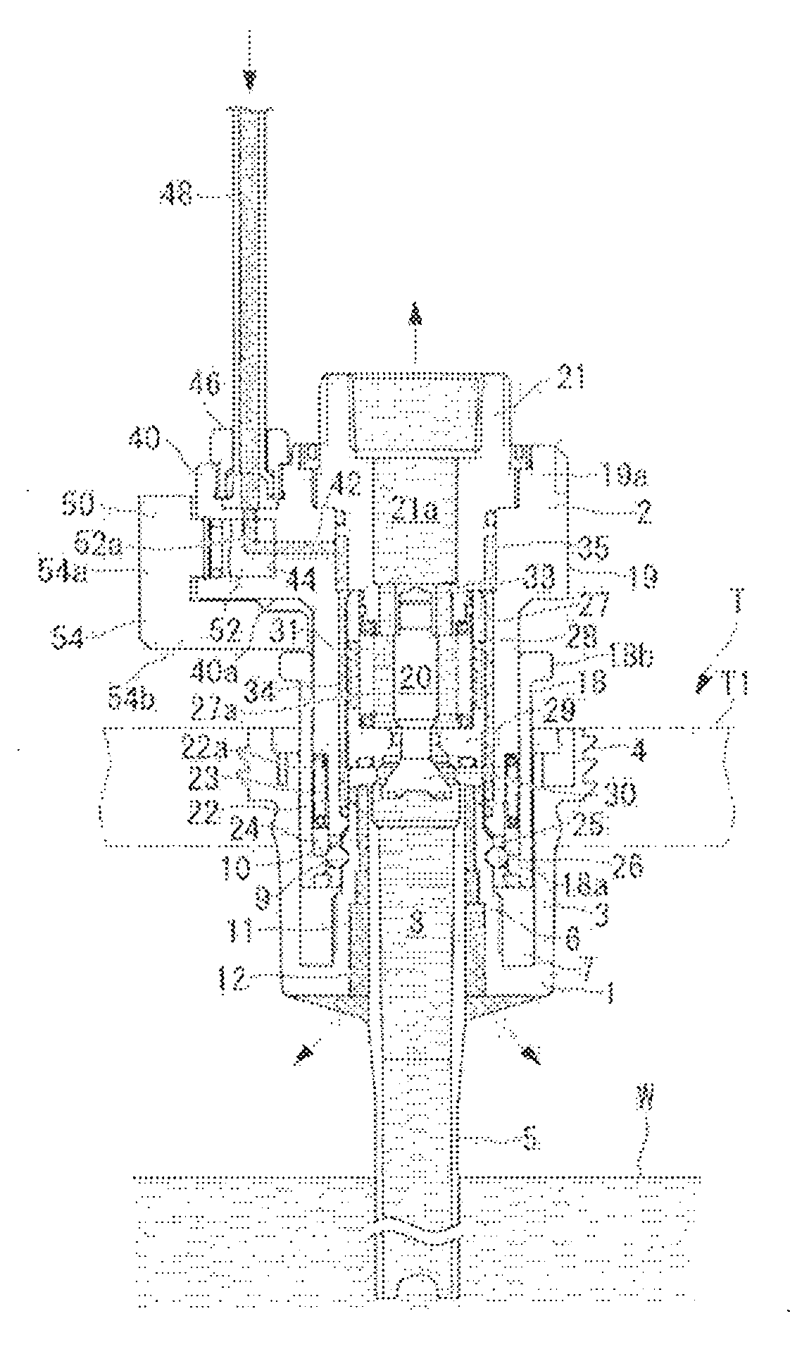
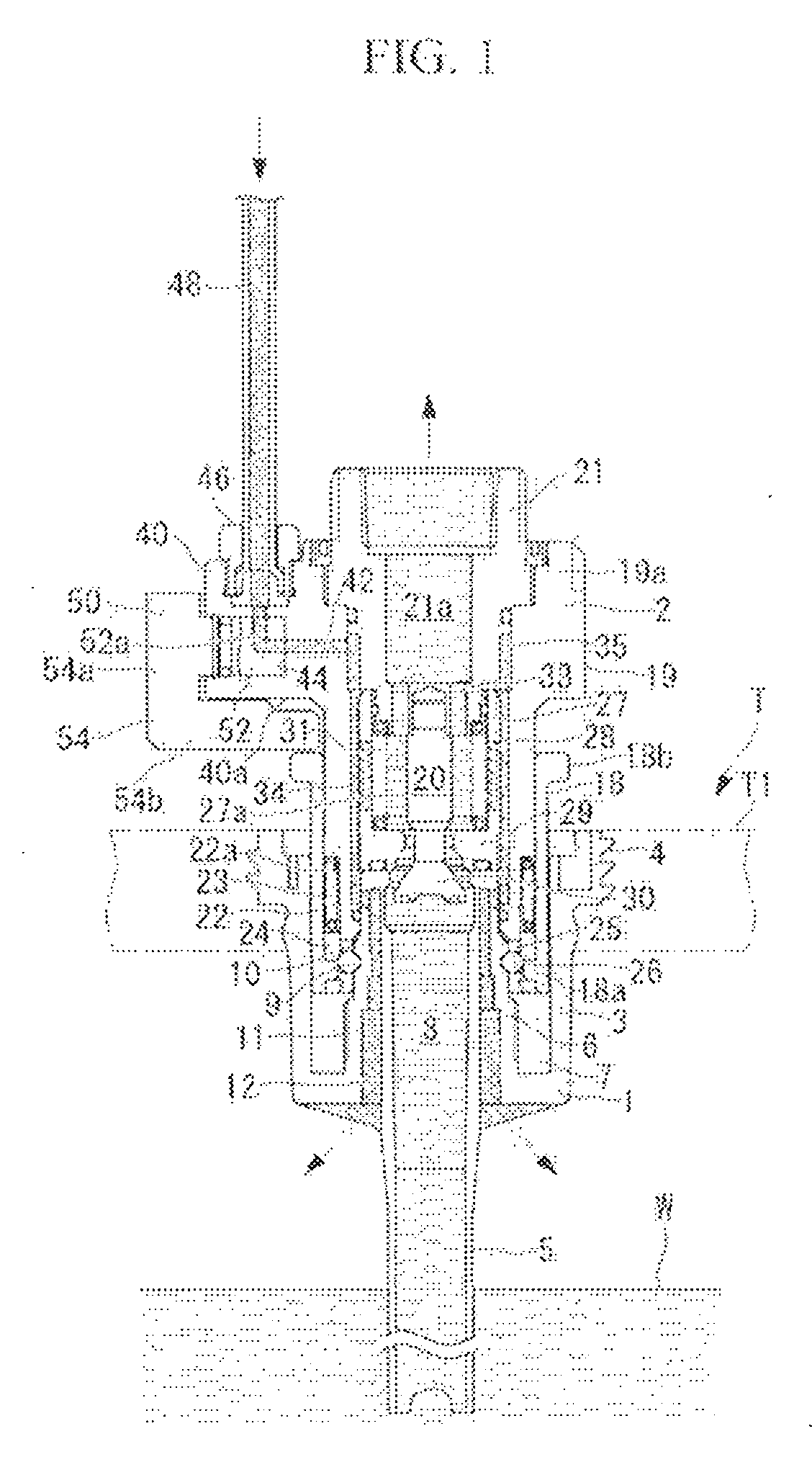
[0046]In FIG. 1, a cross-sectional view of a liquid tank connector according to the embodiment is shown. As shown in the same drawing, a plug 1 is fixed to an upper wall portion T1 of a liquid tank T, and a socket 2 is connected to the plug 1. Drug solution (liquid) W is stored in the liquid tank T.

[0047]The plug 1 is formed of resin and includes a body portion 3 having a cup-shape. A male screw portion 4 is formed on the outer peripheral surface of the body portion 3 for being screwed to the upper wall portion T1 of the tank. A siphon tube 5 formed of resin and extended downward is attached to the center portion of the bottom surface of the body portion 3. The body portion 3 and the siphon tube...


PUM


Abstract

A liquid tank connector for preventing leakage of contents in a liquid tank when removing a socket from a plug fixed to the liquid tank is provided. The liquid tank connector which includes a plug to be fixed to a liquid tank where liquid is stored, a socket which is able to be connected and disconnected with respect to the plug, and a sleeve for releasing a connected state between the plug and the socket by a relative movement with respect to the socket, and in which a liquid flow channels and gas flow channels are formed in a liquid deliverable state in which the plug and the socket are connected, and which includes: a cock which forms a gas flow channel in the liquid deliverable state, and the relative movement of the sleeve is controlled by the position of the cock in the liquid deliverable state.

Description

CROSS REFERENCES TO RELATED APPLICATION[0001]This application is a national phase application based upon priority International PCT Patent Application No. PCT / JP2007 / 067928 filed Sep. 14, 2007, International Publication No. WO 2008 / 035628 A1 published Mar. 27, 2008, which is based upon priority Japanese Patent Application No. JP 2006-252983, filed Sep. 19, 2006.TECHNICAL FIELD[0002]The present invention relates to a liquid tank connector for delivering liquid in a liquid tank to the outside.BACKGROUND OF THE INVENTION[0003]In manufacturing of semiconductors, various chemical agents are used. Such chemical agents are dealt with in a state of being stored in a liquid tank. In semiconductor manufacturing factories equipped with semiconductor manufacturing equipment, the liquid tank is used with a liquid tank connector attached thereto for delivering liquid in the liquid tank to the outside.[0004]FIG. 7 shows a prior art liquid tank with a liquid tank connector attached thereto, such as...

Claims


Application Information

Patent Timeline
Patent Type & Authority Applications(United States)
IPC IPC(8): F16L39/00
CPCB67D7/0283B67D7/3209B67D7/0294Y10T137/314F16L37/22B61D5/08F16L37/40F16L39/00
Inventor TAKANOHASHI, TOSHIYUKIHASUNUMA, MASAHIRO
Owner SURPASS IND
Why Eureka
Try Eureka