Audio signal decorrelator, multi channel audio signal processor, audio signal processor, method for deriving an output audio signal from an input audio signal and computer program

a multi-channel audio signal and decorrelator technology, applied in speech analysis, two-way loud-speaking telephone systems, transmission, etc., can solve the problems of affecting the echo cancellation performance, affecting the quality of the input audio signal, and possesses extremely low complexity

Active Publication Date: 2009-12-10
FRAUNHOFER GESELLSCHAFT ZUR FOERDERUNG DER ANGEWANDTEN FORSCHUNG EV
View PDF12 Cites 309 Cited by
  • Summary
  • Abstract
  • Description
  • Claims
  • Application Information

AI Technical Summary

Benefits of technology

[0046]In other words, the present invention allows to selectively introduce a larger time variant phase shift or time variant delay into the first audio frequency range when compared to the second audio frequency range, thus allowing to set the amplitude of the time variant phase shift or time variant delay as a function of frequency in accordance with the characteristics of the human auditory perception and further in accordance with the requirement for achieving a maximum decorrelation.
[0047]By allowing for a...

Problems solved by technology

As a consequence, a change in the characteristics of a loudspeaker signal xl(k), xp(k) (e.g. due to a change of a geometric position of the sound source 912 in the transmitting room 910) results in a breakdown of the echo cancellation performance and necessitates a new adaptation of the cancellation filters.
While the described scheme (of adding non linear distortions) possesses extremely low complexity, the introduced distortion products can become quite audible and objectionable, depending on the type of audio signal processed.
Typically, the degradation in sound quality is considered acceptable for speech or communication applications, but not for high-quality applications for music signals.
However, the associated implementation complexity and the introduced delay render this approach economically unattractive for most applications.
However, this type of processing generally leads to unacceptable degradations of the stereo image perceived by human listeners, which makes the described processin...

Method used


Image

  • Audio signal decorrelator, multi channel audio signal processor, audio signal processor, method for deriving an output audio signal from an input audio signal and computer program
  • Audio signal decorrelator, multi channel audio signal processor, audio signal processor, method for deriving an output audio signal from an input audio signal and computer program
  • Audio signal decorrelator, multi channel audio signal processor, audio signal processor, method for deriving an output audio signal from an input audio signal and computer program

Examples


first embodiment

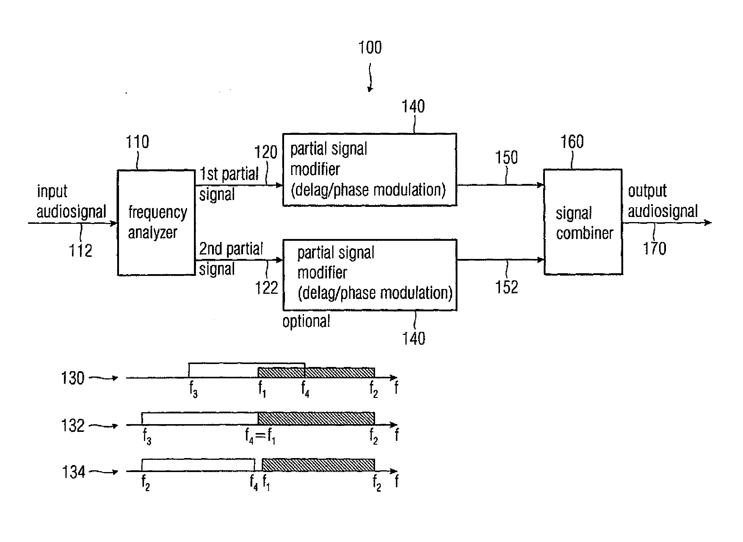
[0081]FIG. 1 shows a block schematic diagram of an inventive audio signal decorrelator according to the present invention. The audio signal decorrelator of FIG. 1 is designated in its entirety with 100. The audio signal decorrelator 100 comprises a frequency analyzer 110, which receives an input audio signal 112. The frequency analyzer 110 analyzes the input audio signal 112 and produces a first partial signal 120 and a second partial signal 122. The first partial signal 120 is descriptive of an audio content in a first audio frequency range, and the second partial signal 122 is descriptive of an audio content in a second audio frequency range.

[0082]The first audio frequency range comprises higher frequencies compared to the second audio frequency range. For example, the first audio frequency range and the second audio frequency range may be contiguous frequency ranges within the audio frequency range of about 10 Hz to 30 kHz.

[0083]For example, the first audio frequency range may co...

second embodiment

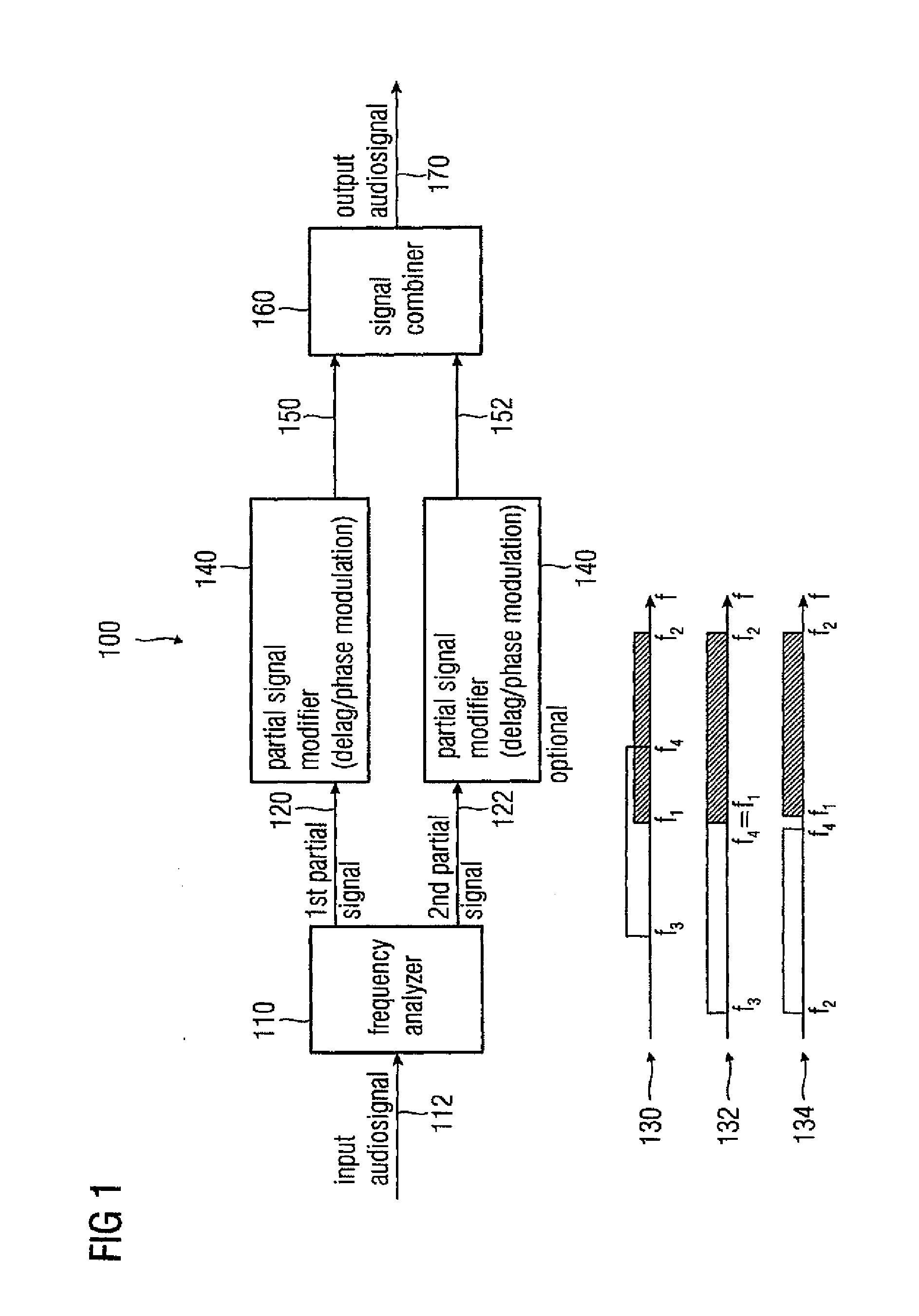
[0092]FIG. 2 shows a block schematic diagram of a multi channel audio signal processor according to the present invention. The multi channel audio signal processor of FIG. 2 is designated in the entirety with 200. The audio signal processor 200 receives a multi channel audio signal, for example a two channel audio signal. For example, the multi channel audio signal processor 200 receives a first channel audio signal 210 and a second channel audio signal 212. The multi channel audio signal processor 200 further comprises a first audio signal decorrelator 220. The first audio signal decorrelator 220 is for example identical to the audio signal decorrelator 100 described with reference to FIG. 1.

[0093]The first audio signal decorrelator 220 provides at its output a first decorrelated output audio signal 230. The multi channel audio signal processor 200 further provides at an output a second decorrelated output audio signal 232, wherein the second decorrelated output audio signal 232 is...

third embodiment

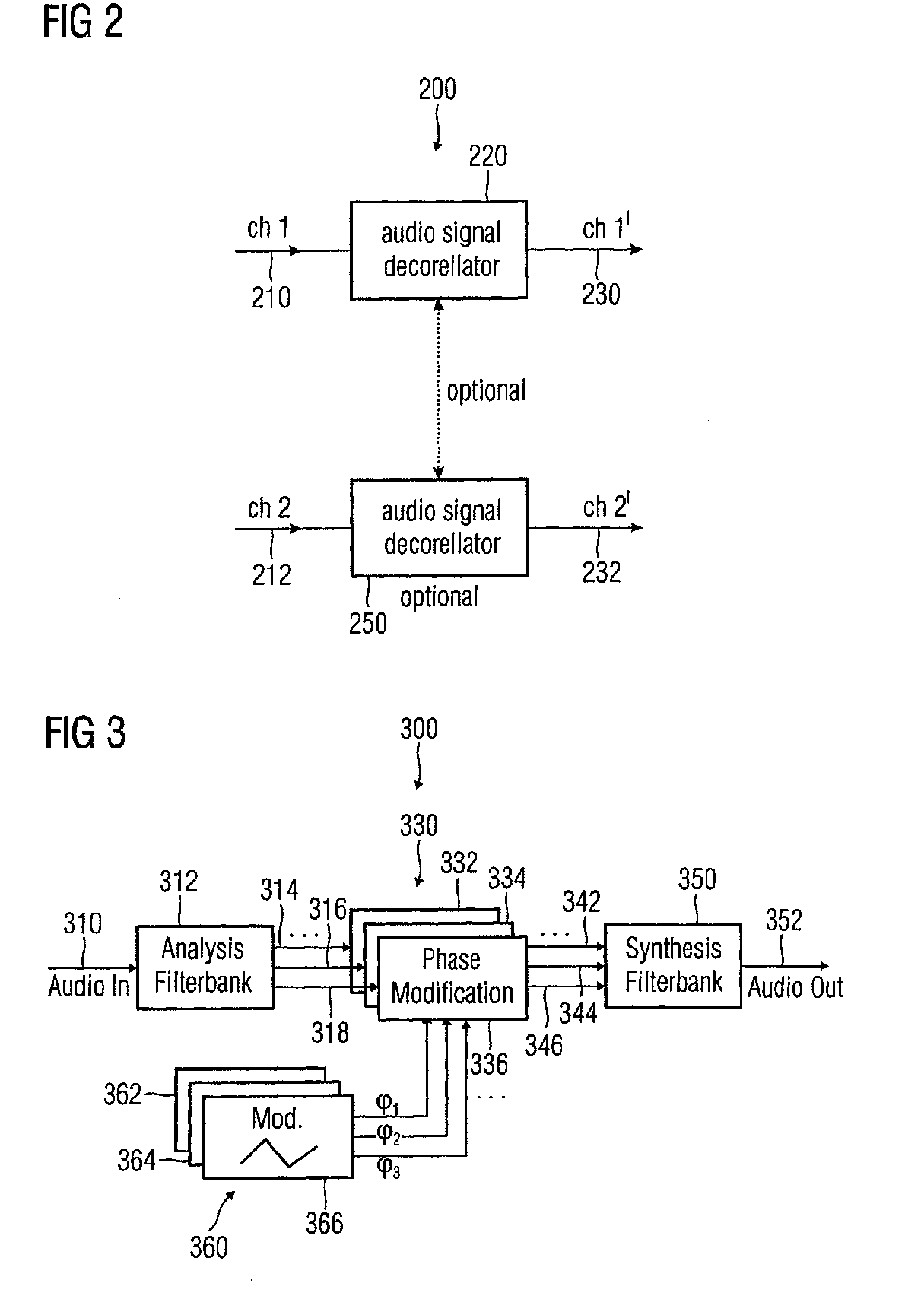
[0098]FIG. 3 shows a block schematic diagram of an inventive audio signal decorrelator, according to the present invention. The audio signal decorrelator of FIG. 3 is designated in a entirety with 300. Audio signal decorrelator 300 receives an input audio signal 310. An analysis filterbank 312 receives the input audio signal 310 and provides at least two (advantageously: more than two) partial signals 314, 316, 318. The partial signals 314, 316, 318 describe audio contents of the input audio signal 310 in different audio frequency ranges, wherein the audio frequency ranges may be overlapping, adjacent or separate, as described with reference to FIG. 1. The analysis filterbank 312 splits up the audio signal 310 in a plurality of partial signals covering different (but possibly overlapping) audio frequency ranges. The partial signals 314, 316, 318 may for example comprise bandpass time signals extracted from different audio frequency ranges of the input audio signal 310. Alternatively...


PUM


Abstract

An audio signal decorrelator for deriving an output audio signal from an input audio signal has a frequency analyzer for extracting from the input audio signal a first partial signal descriptive of an audio content in a first audio frequency range and a second partial signal descriptive of an audio content in a second audio frequency range having higher frequencies compared to the second audio frequency range. A partial signal modifier for modifies the first and second partial signals, to obtain first and second processed partial signals, so that a modulation amplitude of a time variant phase shift or time variant delay applied to the first partial signal is higher than that applied to the second partial signal, or for modifying only the first partial signal. A signal combiner combines the first and second processed partial signals, or combines the first processed partial signal and the second partial signal, to obtain an output audio signal.

Description

BACKGROUND OF THE INVENTION[0001]The present invention is generally related to an audio signal decorrelator, a multi channel signal processor, a five channel audio signal processor, a method for deriving an output audio signal from an input audio signal and a computer program. In particular, the present invention is directed at a convergence enhancement for acoustic echo cancellation (AEC).[0002]In the context of telecommunications and other applications, the problem of acoustic crosstalk between a loudspeaker, which is emitting sound, and a microphone, which is active simultaneously to pick up sound from the same acoustic environment is well-known. As a solution, technology for acoustic echo cancellation (AEC) has been proposed in the past, both for reproduction of a single sound channel (“single-channel AEC”) and for reproduction of two audio channels (“stereo AEC”).[0003]With respect to single channel AEC, reference is taken to the following publications, a detailed list of which...

Claims


Application Information

Patent Timeline
IPC IPC(8): H04B3/20G10L19/00G10L19/008G10L21/02G10L21/0208
CPCG10L19/008H04M9/082G10L2021/02082G10L21/0208H04M9/08
Inventor HERRE, JURGENBUCHNER, HERBERT
Owner FRAUNHOFER GESELLSCHAFT ZUR FOERDERUNG DER ANGEWANDTEN FORSCHUNG EV
Why Eureka
Try Eureka