

Method for forming hollow profiles
a hollow profile and hollow technology, applied in the direction of shafts, mechanical equipment, engine components, etc., can solve the problems of high deformation of the corresponding die, limited deformation degree during such a forming process, and low degree of deformation
- Summary
- Abstract
- Description
- Claims
- Application Information
AI Technical Summary
Benefits of technology
Problems solved by technology
Method used
Image

Examples
Embodiment Construction
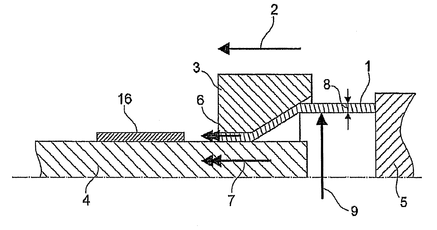
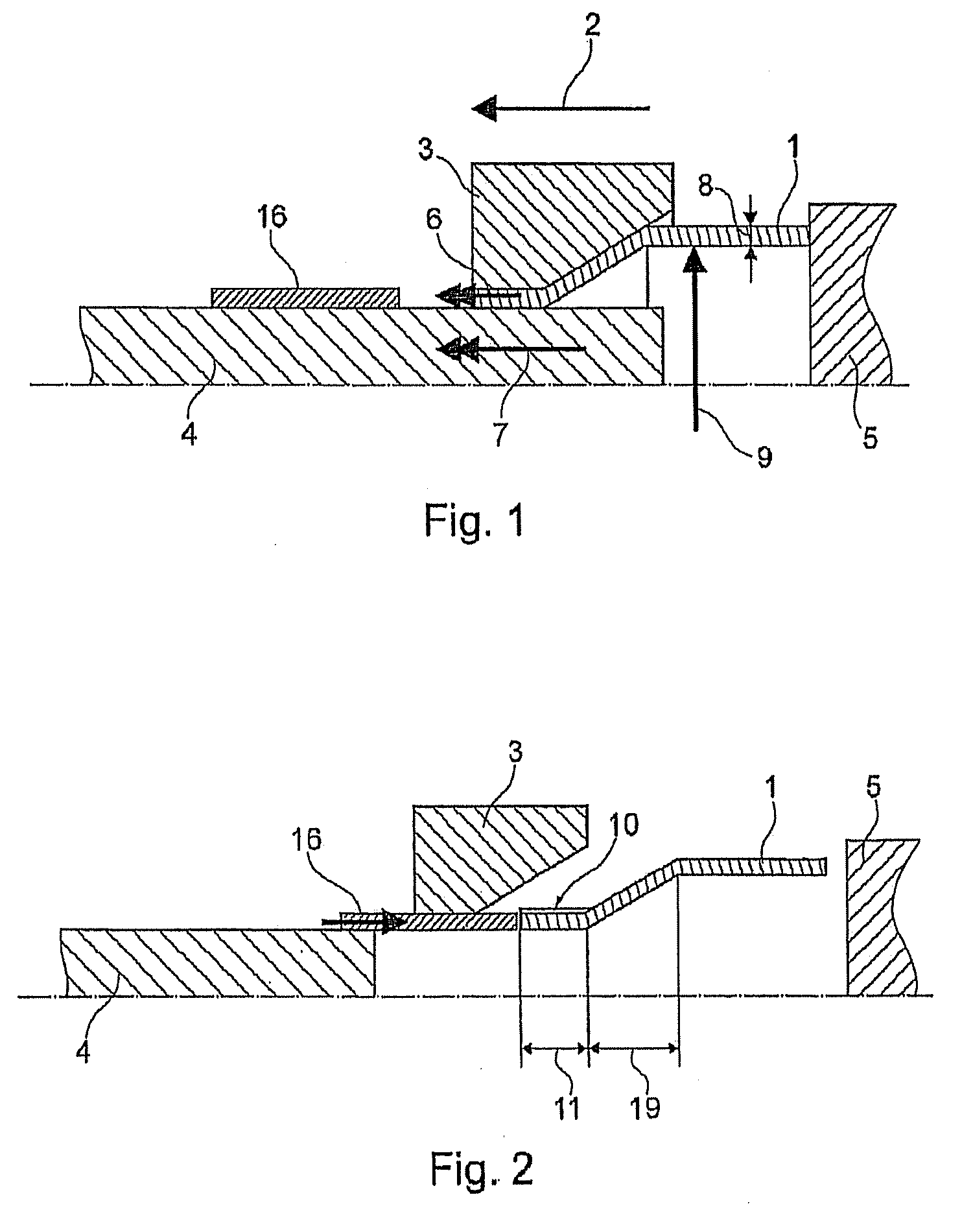
[0032]FIG. 1 is intended to schematically describe the state such as can occur during a forming operation according to the disclosure on a tube-like hollow profile 1. The tool arrangement illustrated comprises a die 3, a ram 5, a mandrel 4 and an ejector 16. The die 3, which is outwardly positioned here with respect to the hollow profile 1, is designed to be fixed, and the hollow profile 1 is forced through the inner orifice of the die 3 (represented in half cross section) by means of the ram 5 bearing at the end face of the hollow profile 1. A forming operation on the hollow profile 1, which has a predetermined wall thickness 8, now takes place at the die 3 such that a reduction in the diameter 9 occurs.
[0033]To obtain a controlled forming operation, the mandrel 4 is arranged inside the die 3, namely concentrically with respect to orifice of the die 3, such that the die 3 and mandrel 4 form a gap through which the hollow profile 1 is forced. During the process, a material flow velo...
PUM
| Property | Measurement | Unit |
|---|---|---|
| Temperature | aaaaa | aaaaa |
| Thickness | aaaaa | aaaaa |
| Thickness | aaaaa | aaaaa |
Abstract
Description
Claims
Application Information