Cangrier-M1 machine or C-M1 the powerful miracle perpetual motion machine designed for hydroelectric power generation water recycling concept

a technology perpetual motion, which is applied in the direction of couplings, rotary clutches, fluid couplings, etc., can solve the problems of affecting the efficiency of hydroelectric power generation, so as to achieve the effect of reducing blackouts and brownouts, reducing construction costs, and ensuring the safety of mankind

Inactive Publication Date: 2009-12-17
TIMCANG MISS MARY GRACE
View PDF4 Cites 1 Cited by
  • Summary
  • Abstract
  • Description
  • Claims
  • Application Information

AI Technical Summary

Benefits of technology

[0003]C-M1 is by far incomparable to known conventional prime movers. C-M1, unlike fossil fuel base engines and nuclear power plant, does not pollute air and water. It does not produce sound, heat, smoke, waste, and radiation. Therefore, it does not contribute to air, water, and noise pollution and global warming. It does not cause fire and explosion because it uses only water. Therefore, it is 100% safe to mankind. Compared to known renewable energies such as hydro, geothermal, solar, wind, sea wave, and sea current, all of which have drawbacks, C-M1 does not have any from its power source, which is gravity because it is consistent. Moreover, compared to a hydroelectric having the same capacity, it is 40% to 60% cheaper and 6 to 7 times faster to build when it comes to power generation. Since it is a low RPM machine and has 7 about moving parts, it can even last for a century without breakdown. Therefore, blackouts and brownouts are minimized. Because C-M1 is a noise-free machine, it can be built within a city or urban area. Due to this, expensive pylons, transmission lines and equipments can be minimized or eliminated.

Problems solved by technology

I have also read and heard about perpetual motion machines run by gravity, spring, flywheel, magnet, electromagnet, but all are bulky and impractical.
I concentrated on known renewable energies as well, but all have drawbacks and limitations.
The same problem will occur!
Only this time, the problem is shifted to the counterweight instead of the weight of the water inside the system.

Method used


Image

  • Cangrier-M1 machine or C-M1 the powerful miracle perpetual motion machine designed for hydroelectric power generation water recycling concept
  • Cangrier-M1 machine or C-M1 the powerful miracle perpetual motion machine designed for hydroelectric power generation water recycling concept
  • Cangrier-M1 machine or C-M1 the powerful miracle perpetual motion machine designed for hydroelectric power generation water recycling concept

Examples


Embodiment Construction

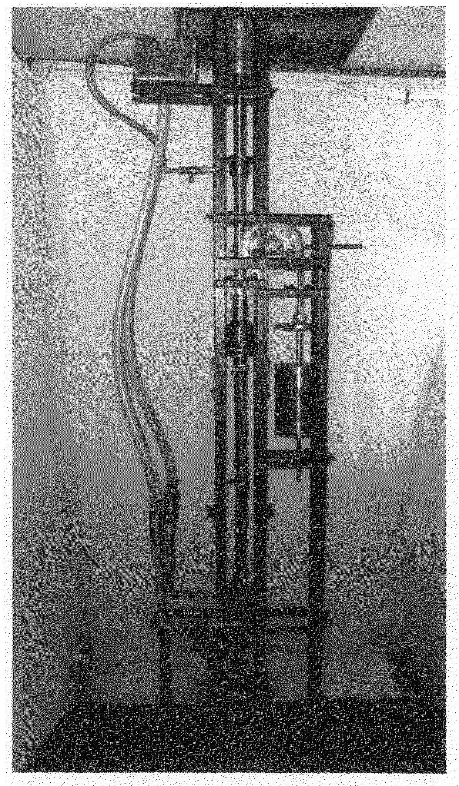
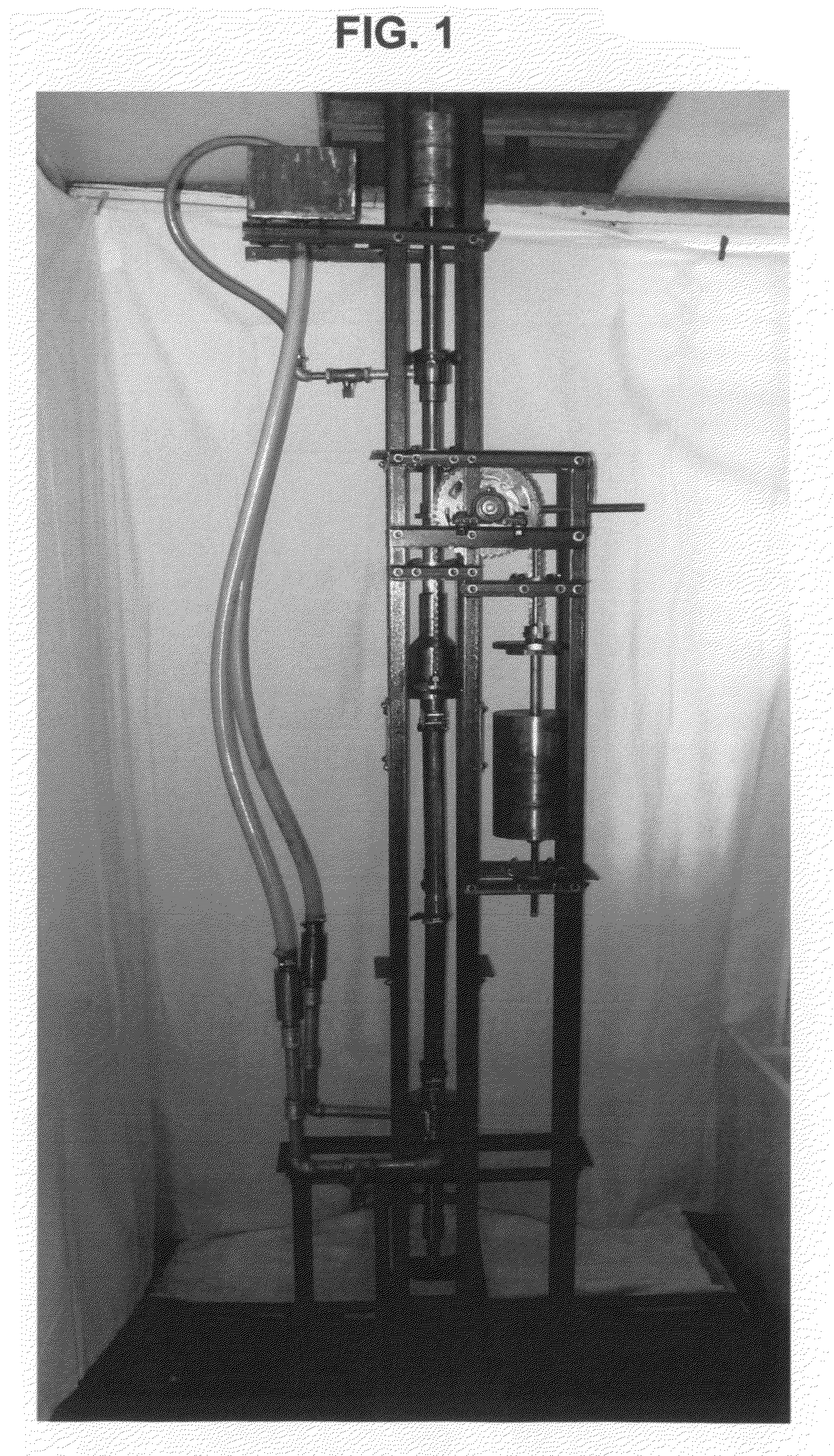
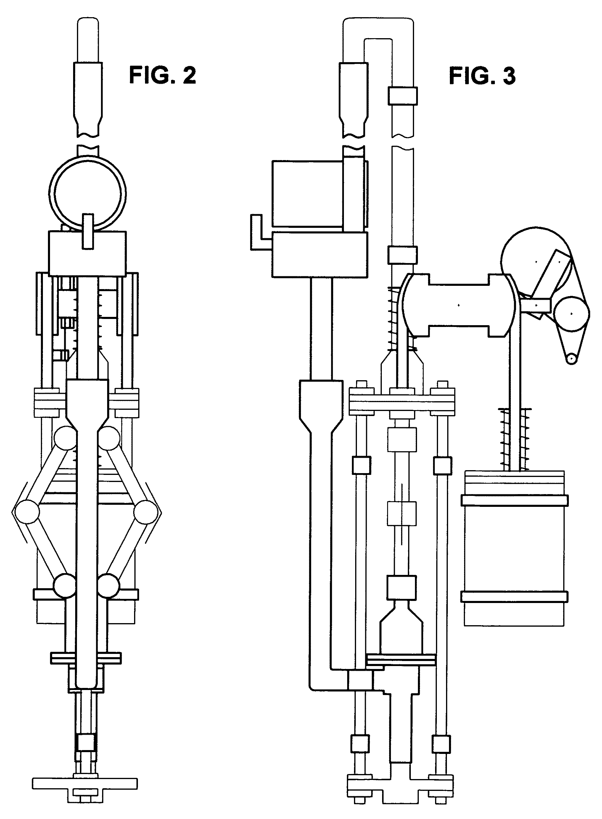
[0028]In all honesty, C-M1's technical aspect is simple. In fact, in my actual explanation and demonstration to my selected kin on how C-M1 works, I needed only 10 minutes. C-M1 is basic of all basics machine, working primarily on the Techniques and the underlying Principle of Equilibrium. But how does C-M1 handle the Input / Intake and Output / Discharge Operations, the known problem since man has existed? C-M1 has employed simple Techniques that have not been discovered since time immemorial. These techniques are fully described and consolidated in the illustration of C-M1 Embodiments.[0029]A) C-M1 Parts[0030]B) C-M1 Components[0031]C) C-M1 Types of Perpetual Motion Machine[0032]D) C-M1 Operation Defined and Described[0033]E) C-M1 Choice of Presentation[0034]F) C-M1 Housekeeping[0035]G) C-M1 Embodiments

A) C-M1 Parts—C-M1 is Divided into 11 Major Parts and 44 Subparts:[0036]1 Piston—draws water from the Storage / Supply Tank 10A down to the Cylinder / Storage Chamber 2 during the Input / Int...


PUM


Abstract

When water is pumped manually to the overhead tank, the weight of the water is felt on the opposite end of the lever. Thus, an equal or heavier weights to counter that weight is thought of. This idea works on the output process but not on the input process. However, unlike conventional water pumps, C-M1 works on both processes using techniques (the invention) that employ the underlying principle of equilibrium or perfect balance. These techniques have resulted to the discovery of C-M1, a very powerful perpetual motion machine capable of using equal or heavier weights to counter the weights on the other end of the lever on both the input and output operations. Therefore, since it is perfectly balance, pumping out 1 cubic meter of 10 water per stroke through a 1.6-meter diameter 500-meter high pipe, with a total water weight of 1,000 tons, is simple and easy job for C-M1.

Description

BACKGROUND OF THE INVENTION[0001]My quest for a machine that runs without the need of any fossil fuel, nuclear, or any prime mover that needs consumable materials or elements, started in August 1970 in my Earth Science subject. It started when one of my classmates raised the question on how to control air, water and noise pollution and radiation. Then somebody answered: “Ma'am, through perpetual motion machine!”. Thenceforth, my research and study for that elusive machine has been born and intensified. Time, effort, and money were all focused on how to discover such machine. I have also read and heard about perpetual motion machines run by gravity, spring, flywheel, magnet, electromagnet, but all are bulky and impractical. I concentrated on known renewable energies as well, but all have drawbacks and limitations. Because of these imperfections, my research and experiment persisted. I continued such endeavor when I worked in Bahrain and Saudi Arabia, and when I was back to the Philip...

Claims


Application Information

Patent Timeline
Patent Type & Authority Applications(United States)
IPC IPC(8): F03B17/04H02K53/00
CPCY02E10/20F03B17/005
Inventor TIMCANG, SR., EDGARDO CO
Owner TIMCANG MISS MARY GRACE
Why Eureka
Try Eureka