Humidity control system

a humidity control system and humidity control technology, applied in the direction of heating types, domestic cooling devices, separation processes, etc., can solve the problems of adsorption heat exchanger surface freezing, adsorption heat exchanger peeling off, adsorption heat exchanger surface deterioration, etc., to achieve the effect of enhancing the dehumidification capacity of the humidity control system, reducing the temperature, and effective increasing the temperatur

Active Publication Date: 2009-12-17
DAIKIN IND LTD
View PDF2 Cites 7 Cited by
  • Summary
  • Abstract
  • Description
  • Claims
  • Application Information

AI Technical Summary

Benefits of technology

[0020]In the present invention, air flows through the adsorption heat exchanger (51, 52) during the regeneration action from a side thereof into which the heat transfer medium flows towards a side thereof out of which the heat transfer medium flows. Therefore, according to the present invention, the air can be effectively increased in temperature at the air inflow end of the adsorption heat exchanger (51, 52). Thus, even when extremely low-temperature outdoor air passes through the adsorption heat exchanger (51, 52) such as in winter, the outdoor air can be increased to a relatively high temperature at the air inflow end of the adsorption heat exchanger (51, 52). Therefore, dew condensation water can be prevented from freezing on the surface of the adsorbent on the adsorption heat exchanger (51, 52), thereby preventing the adsorbent from being deteriorated and from peeling off from the adsorption heat exchanger (51, 52).
[0021]In the second aspect of the invention, air flows through the adsorption heat exchanger (51, 52) during the adsorption action from a side thereof into which the heat transfer medium flows towards a side thereof out of which the heat transfer medium flows. Therefore, according to the second aspect, the air can be effectively reduced in temperature at the air inflow end of the adsorption heat exchanger (51, 52). Thus, the air temperature can be reduced to smaller than the dew point at the air inflow side of the adsorption heat exchanger (51, 52) to condense moisture in the air into dew and dehumidify the air. Therefore, the dehumidification capacity of the humidity control system can be enhanced. Hence, even if air cannot be well dehumidified only by the dehumidification capacity of the adsorbent, moisture can be condensed in dew to compensate for the shortage of the dehumidification capacity of the adsorbent.
[0022]According to the third aspect of the invention, air flows through the adsorption heat exchanger (51, 52) during the adsorption action from a side thereof out of which the heat transfer medium flows towards a side thereof into which the heat transfer medium flows. Therefore, according to the third aspect, the air cooling effect of the adsorption heat exchanger (51, 52) can be enhanced. Hence, the air can be effectively cooled and dehumidified by the adsorption heat exchanger (51, 52) during the adsorption action, whereby room can be effectively cooled, for example, during a dehumidification operation in summer.
[0023]According to the fourth aspect of the invention, the refrigerant circuit (50) operable in a refrigeration cycle is used as the heat transfer medium circuit. Therefore, the adsorbent can be effectively cooled by refrigerant evaporating in the adsorption heat exchanger (51, 52), thereby enhancing the adsorption capacity of the adsorbent. Furthermore, the adsorbent can be effectively heated by refrigerant condensing in the adsorption heat exchanger (51, 52), thereby enhancing the regeneration capacity of the adsorbent.

Problems solved by technology

Therefore, when extremely low-temperature outdoor air passes through the above adsorption heat exchanger such as in winter, moisture having condensed into dew around the adsorption heat exchanger may freeze on the surface of the adsorbent.
However, if such moisture freezing and melting on the adsorbent surface are repeated, the adsorbent might gradually deteriorate and in turn peel off from the surface of the adsorption heat exchanger.

Method used


Image

  • Humidity control system
  • Humidity control system
  • Humidity control system

Examples


embodiment 1

Effects of Embodiment 1

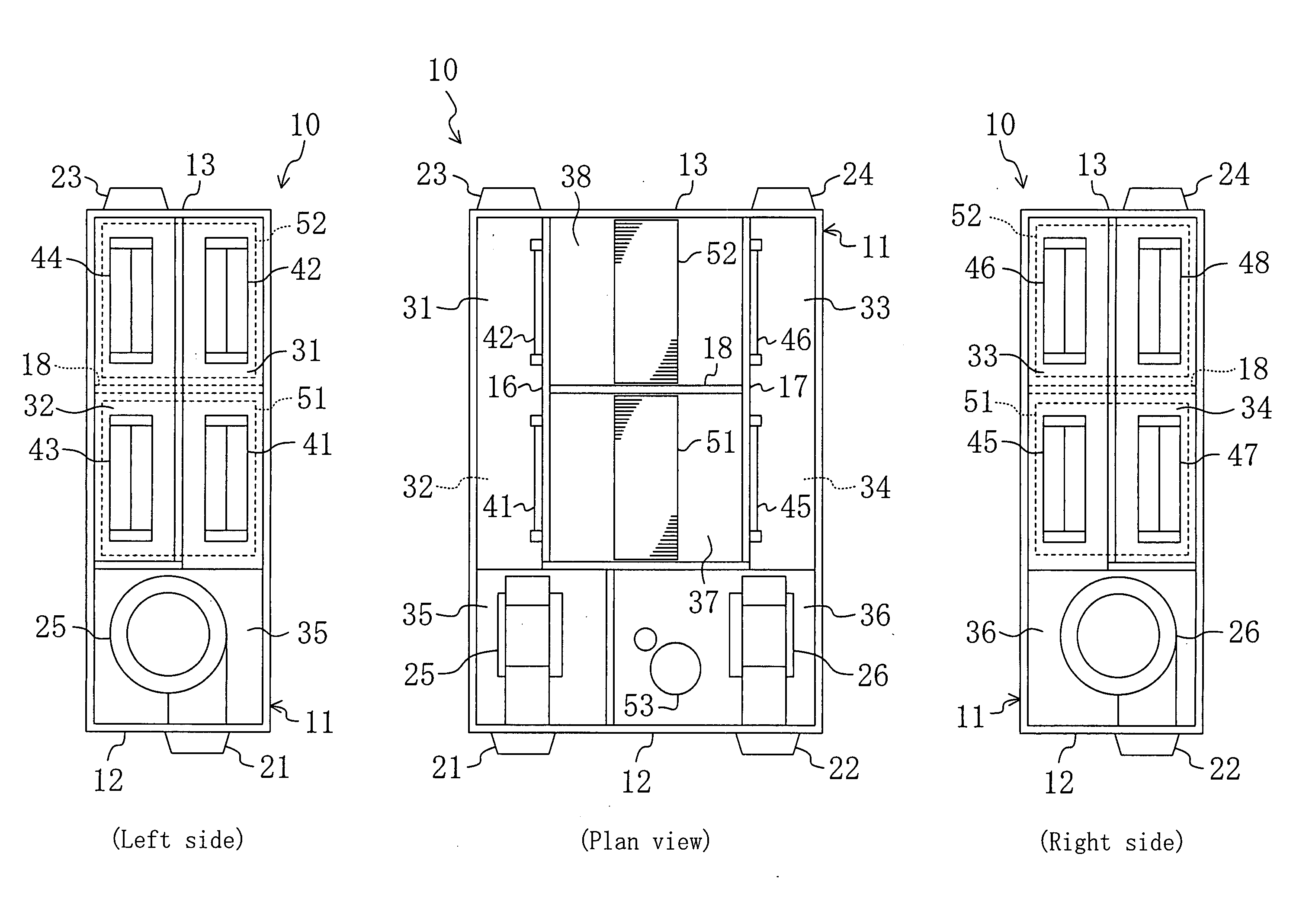
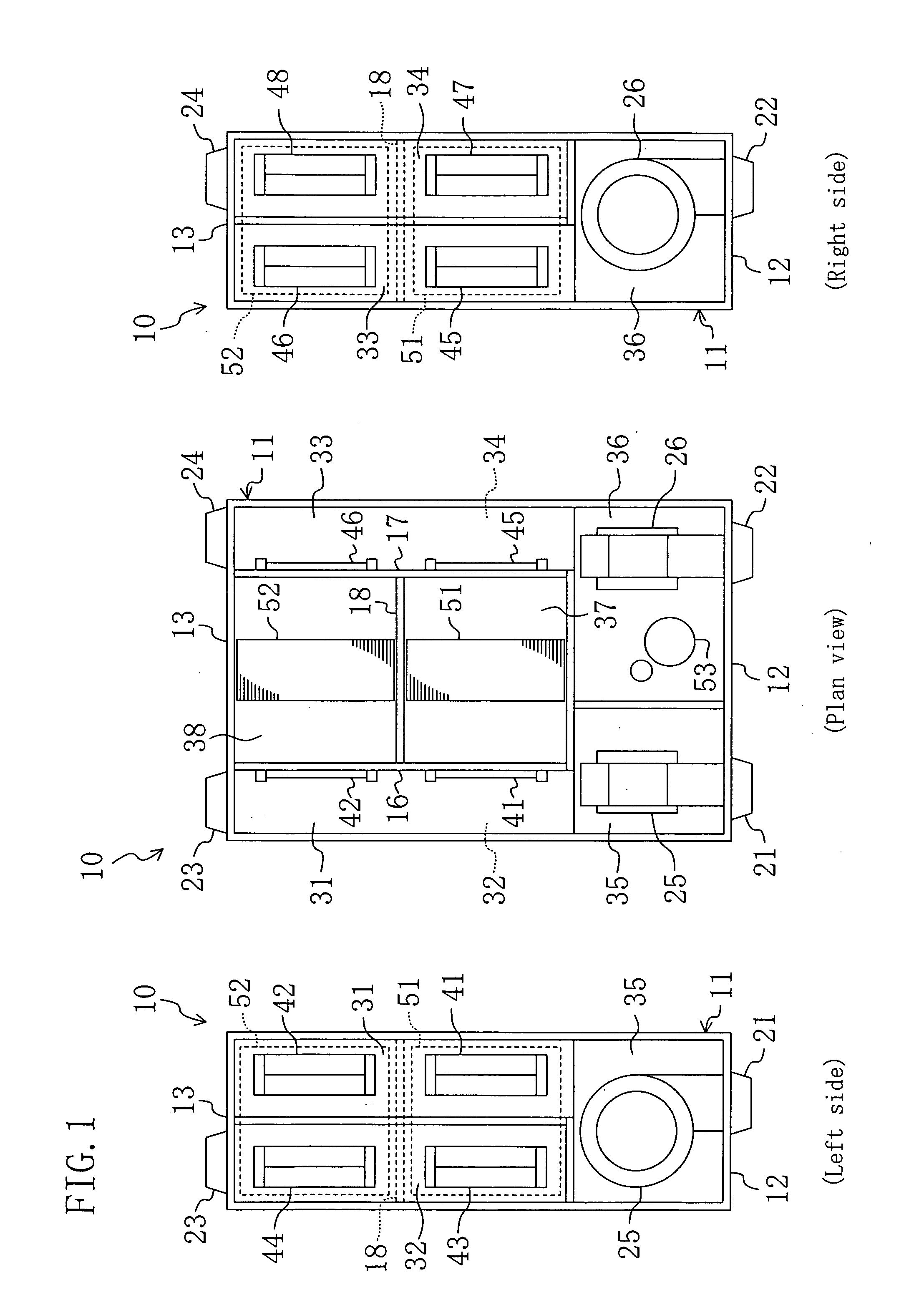
[0099]According to Embodiment 1, outdoor air flows in the adsorption heat exchanger (51, 52) serving as a condenser during the regeneration action of the humidification operation from upstream to downstream in the flow of refrigerant. Therefore, the air can be effectively increased in temperature at the air inflow end of the adsorption heat exchanger (51, 52). Thus, even when extremely low-temperature outdoor air passes through the adsorption heat exchanger (51, 52) such as in winter, the outdoor air can be increased to a relatively high temperature at the air inflow end of the adsorption heat exchanger (51, 52). Therefore, dew condensation water can be prevented from freezing on the surface of the adsorbent on the adsorption heat exchanger (51, 52), thereby preventing attendant deterioration of the adsorbent and the binder bonding the adsorbent to the heat exchanger body. Hence, the adsorbent can be prevented from peeling off from the adsorption heat exchange...

embodiment 2

Modification of Embodiment 2

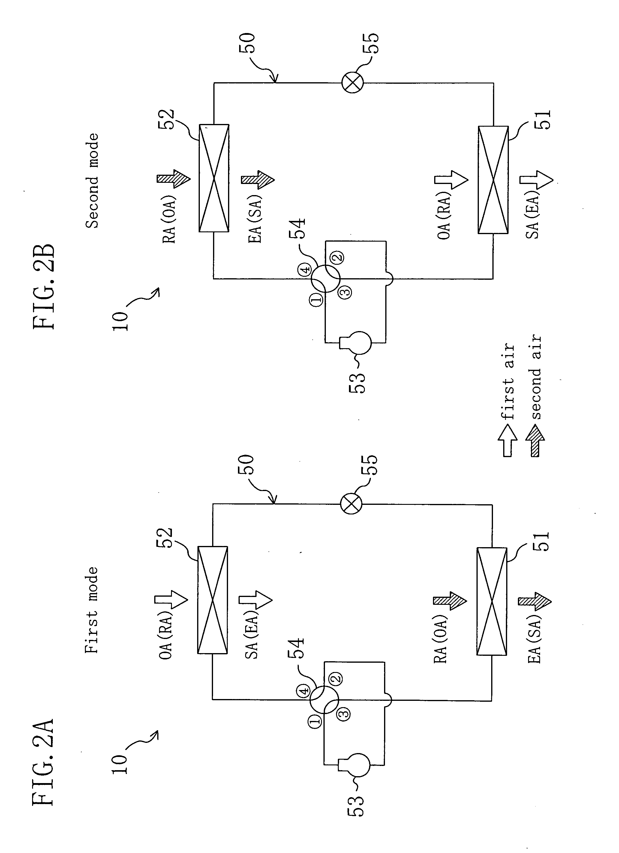
[0137]Instead of the refrigerant circuit of Embodiment 2, a refrigerant circuit (50) shown in FIG. 17 may be applied to the humidity control system (10). In the refrigerant circuit (50) of this modification, a second four-way selector valve (56) is connected in addition to the elements of the refrigerant circuit (50) of the above embodiment.

[0138]In the refrigerant circuit (50), the compressor (53) is connected at its discharge side to a first port of a first four-way selector valve (54) and connected at its suction side to a second port of the second four-way selector valve (56). The first adsorption heat exchanger (51) is connected at one end to a third port of the first four-way selector valve (54) and connected at the other end to a third port of the second four-way selector valve (56). The second adsorption heat exchanger (52) is connected at one end to a fourth port of the first four-way selector valve (54) and connected at the other end to a fourth...


PUM


Abstract

A humidity control system (10) includes a refrigerant circuit (50) in which an adsorption heat exchanger (51, 52) carrying an adsorbent thereon is connected. During a regeneration action of a humidification operation of the humidity control system (10), outdoor air passes through the adsorption heat exchanger (51, 52) from upstream towards downstream in the flow of refrigerant. Therefore, the air can be effectively increased in temperature at the air inflow end of the adsorption heat exchanger (51, 52), thereby preventing freezing of dew condensation water.

Description

TECHNICAL FIELD[0001]This invention relates to humidity control systems including an adsorption heat exchanger carrying an adsorbent thereon and particularly relates to humidity control systems capable of regenerating the adsorbents on their adsorption heat exchangers by bringing them into contact with air.BACKGROUND ART[0002]Humidity control systems are conventionally known that control the humidity of a room by adsorbing and desorbing moisture in air.[0003]For example, Patent Document 1 discloses a humidity control system including a refrigerant circuit in which adsorption heat exchangers each carrying an adsorbent thereon are connected. In the refrigerant circuit of the humidity control system, a compressor, a first adsorption heat exchanger, an expansion valve, a second adsorption heat exchanger and a four-way selector valve are connected. The refrigerant circuit operates in a refrigeration cycle by circulating refrigerant therethrough. Out of the two adsorption heat exchangers,...

Claims


Application Information

Patent Timeline
Patent Type & Authority Applications(United States)
IPC IPC(8): F25B15/00
CPCF24F3/001F24F3/1411F24F3/1429Y02B30/72F24F13/30F25B13/00F25B2341/0653Y02B30/70F25B41/35F24F3/14B01D53/26B01D53/28
Inventor MATSUI, NOBUKIISHIDA, SATOSHIYABU, TOMOHIRO
Owner DAIKIN IND LTD
Why Eureka
Try Eureka