Watercraft with wave deflecting hull

Inactive Publication Date: 2009-12-17
BAKER ELBERT H
View PDF26 Cites 11 Cited by
  • Summary
  • Abstract
  • Description
  • Claims
  • Application Information

AI Technical Summary

Benefits of technology

[0015]The wave spreading hull portions have a forward apex which forms a substantially perpendicular or vertical leading wedge to the plane of water. Since the apex and planes of the wedge shaped hull portions are substantially perpendicular to the water, oncoming waves encountered by the hull portions will tend to be deflected horizontally. Accordingly, the watercraft will more easily “cut through” waves instead of riding over them.
[0016]Located rearwardly of the wave spreaders, an internal hull prow portion is spaced from the wave spreading surfaces, creating an air space therebetween. The air space extends from the rearward surface of the wave spreader to the front of internal hull prow, creating a dampening space to further minimize any wave action not deflected by the hull portions. The internal hull prow portion extends to a flat-bottomed section of the hull. The air space further eliminates any surface that would tend to ride up onto a wave.
[0017]The portion of the hull that contacts water while the watercraft is at cruising speed is spaced rearwardly of the air space. This portion of the hull that contacts the water is generally flat, as opposed to the V-shape commonly found in watercraft. This flat-bottomed hull enables the watercraft to easily reach a plane, while displacing a smaller amount of water than typical V-shaped hulls. The multi-hull design according to the invention also facilitates displacement of water between hulls, to further minimize forces acting on the boat.

Problems solved by technology

Such designs have been used for years, but have various deficiencies.
One detriment to such hull designs is that the draft of the boat tends to sit relatively deep in the water in relation to the length and beam of the boat, thus requiring sufficient depth of water to accommodate that draft.
Another detriment to such hull designs is that they require a relatively large amount of force (and horsepower) to propel such a boat forward at a sufficient speed to stabilize the boat, i.e., to force the water sideways and downwardly as the boat travels generally horizontally through the water.
However, in all cases, the forward movement of the boat, at any speed, whether up on plane or not, is counteracted by both sideways and downward vectors of force produced by the relative hydraulic movement of the water against the hull.
The greater those forces, the greater will be the amount of fuel consumed.
The down side is that, because bass boats are relatively narrow beamed and because there is relatively little sideways or lateral force being exerted against the hull of a bass boat, there is correspondingly less lateral stability, and, due to a relatively narrow beam, such boats tend to be susceptible to laterally moving waves.
Such flat bottom hulls are also generally more susceptible to waves as the hull rides more on top of the waves rather than slicing somewhat through waves as V-shaped hulls do to a greater degree.
Also, such boats do not steer as easily or as precisely as those with distinct, V-shaped hulls, due again to the fact that such boats incur relatively less opposing sideways forces, being those forces which tend to hold a boat to a straight forward movement.
Therefore, when steered to turn, bass boats tend to skid laterally sideways more readily, thus making turning a much less precise and controllable skidding action, rather than the positive, more precisely controllable action of V-shaped hulls.
Both types of hulls are susceptible to wave action and may produce instability depending on the height and direction of waves.
Both types of hulls have large surfaces which absorb the force of waves, and cause significant vibration, vertical or lateral movement, or a combination of these.
Other boats include hull designs which incorporate pontoons or sponsons for lateral stability and floatation, but such systems are undesirable for a number of reasons.

Method used


Image

  • Watercraft with wave deflecting hull
  • Watercraft with wave deflecting hull
  • Watercraft with wave deflecting hull

Examples


Embodiment Construction

[0029]Reference will now be made in detail to an embodiment of the invention as illustrated in the accompanying drawings.

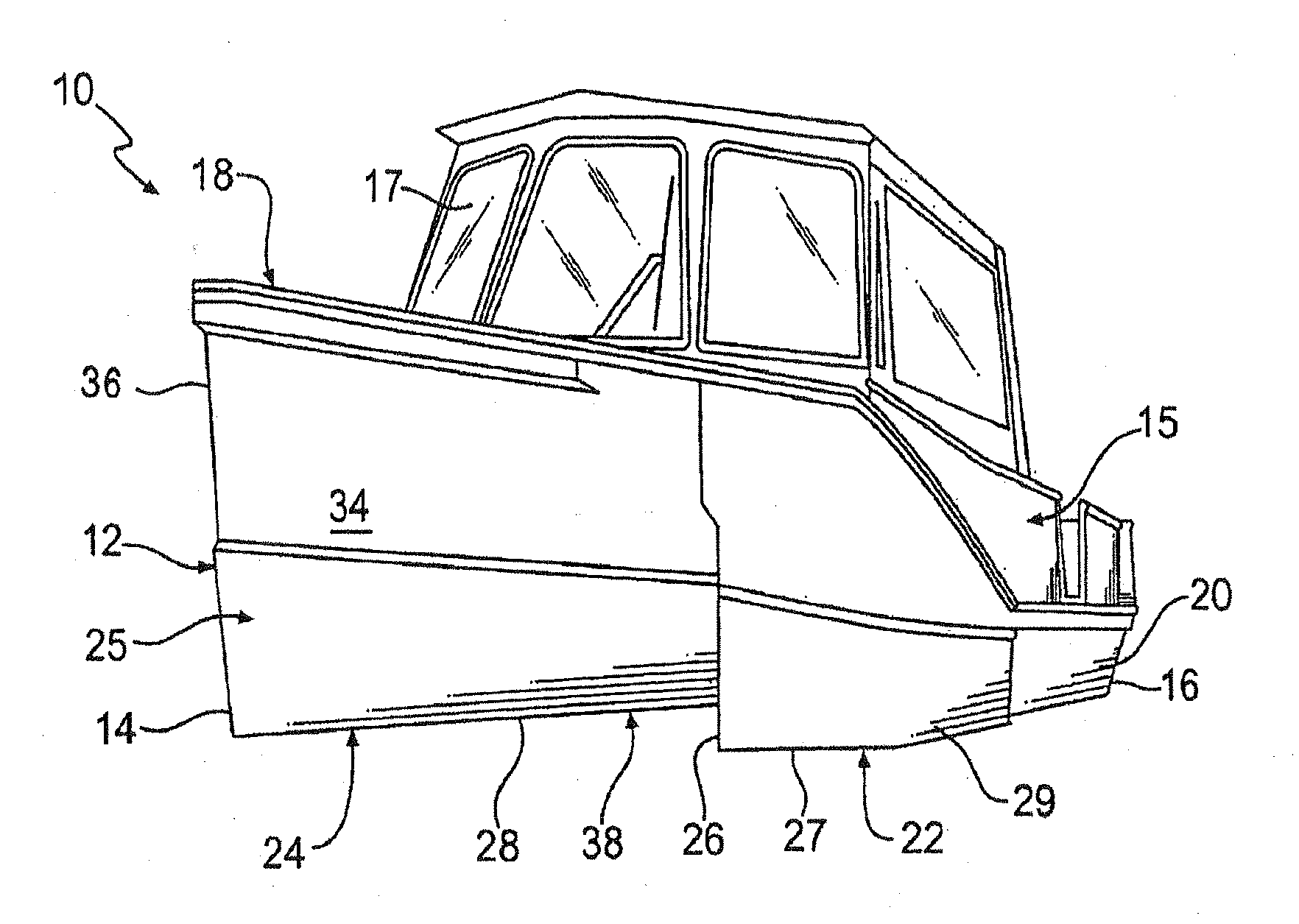
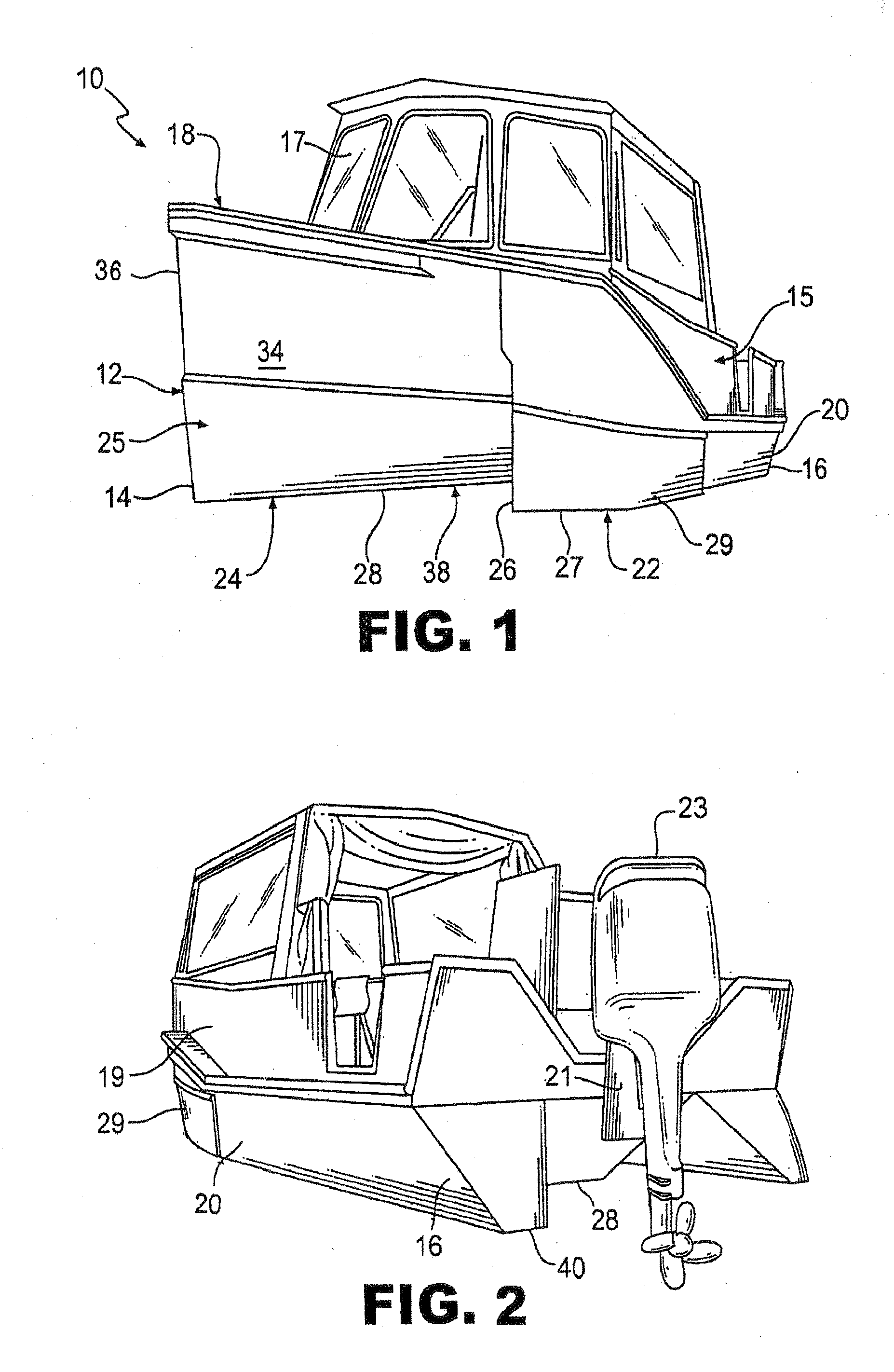
[0030]Turning to FIGS. 1-2, an embodiment of a watercraft, generally identified by reference number 10, is illustrated. The watercraft 10 comprises a hull 12 having a bow 14, stern, 16, port side 18, and starboard side 20. The watercraft 10 may be built out of aluminum with a formed hull or sheets with welded seams. The hull 12 and other portions of watercraft 10 could also be fabricated from other materials such as, for example, FRP, high-density polyethylene, other metals, or other suitable materials.

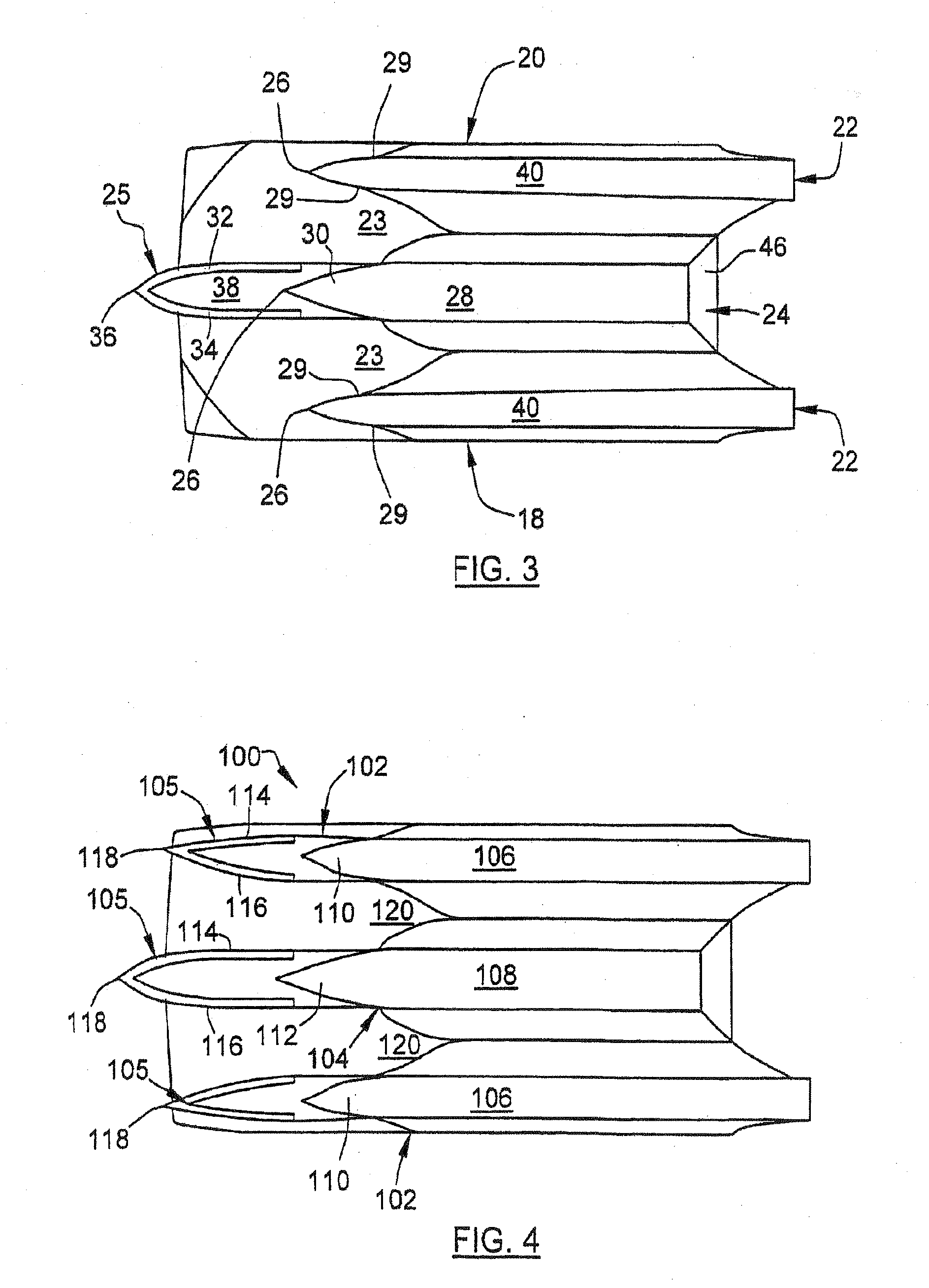
[0031]As illustrated in FIGS. 1 and 2, and with reference to the schematic of the hull configuration in FIG. 3, the watercraft 10 comprises a hull 12 which is designed to cut through waves or wakes of other boats, and minimize the forces acting on the hull to reduce the pounding experienced with typical hull designs. The hull 12 further reduces lateral action on the...


PUM


Abstract

The invention is directed to a watercraft hull design that comprises a hull having a bow, stern, top, and bottom. A wedge-shaped wave spreading system is located at a forward portion of the craft. The wave-contacting surface planes of the wave spreading system are positioned substantially perpendicular to the plane of smooth water. The bottom edge of the wave spreading system is positioned near the level of smooth water when the watercraft is at cruising speed. The wave spreading system has a forward apex which forms a substantially perpendicular or vertical leading wedge to the plane of water. Since the apex and planes of the wave spreader are substantially perpendicular to the water, oncoming waves encountered by the wave spreader will tend to be deflected horizontally. Accordingly, the watercraft will more easily “cut through” waves instead of riding over them. Located rearwardly of the wave spreader, an internal hull prow is spaced from the wave spreading system, creating an air space therebetween. The air space extends from the rearward surface of the wave spreader to the front of internal hull prow, creating a buffer zone or dampening space to further minimize any wave action not detected by the spreading system.

Description

CROSS-REFERENCE TO RELATED APPLICATIONS / INCORPORATION BY REFERENCE[0001]This U.S. patent application is a continuation-in-part of and claims priority to pending U.S. patent application Ser. No. 12 / 057,039 filed on Mar. 27, 2008 which is incorporated herein by reference in its entirety, which is a continuation-in-part of U.S. patent application Ser. No. 11 / 028,274 filed on Jan. 3, 2005, now U.S. Pat. No. 7,188,575 issued on Mar. 13, 2007. U.S. Pat. No. 7,188,575 is incorporated herein by reference in its entirety.TECHNICAL FIELD[0002]The present invention relates generally to watercraft. More specifically, the present invention relates to watercraft hulls designed to displace water in a manner to provide enhanced stability and movement through the water.BACKGROUND OF THE INVENTION[0003]Conventional recreational and commercial watercraft, for the most part, incorporate hulls which have V-shaped bottoms, with the V-shape, at its lowest point, forming a keel. The V-shape is thought to e...

Claims


Application Information

Patent Timeline
IPC IPC(8): B63B1/40
CPCB63B1/042
Inventor BAKER, ELBERT H.
Owner BAKER ELBERT H
Why Eureka
Try Eureka