
Heat pipe with a dual capillary structure and manufacturing method thereof

a technology of capillary structure and heat pipe, which is applied in the direction of machines/engines, speed sensing governors, light and heating apparatus, etc., can solve the problems of increasing heat generation, affecting heat conducting performance, and fan cannot meet the requirements of present central processing units, so as to improve heat conducting speed and performance, prevent capillary structure collapse, and improve structural strength

Inactive Publication Date: 2009-12-17
CHAUN CHOUNG TECH
View PDF4 Cites 40 Cited by
  • Summary
  • Abstract
  • Description
  • Claims
  • Application Information

AI Technical Summary

Benefits of technology

[0009]It is a primary objective of the present invention to overcome the foregoing shortcomings by providing a heat pipe with a dual capillary structure and its manufacturing method, and a dense capillary structure is formed in a heat-absorption part of the metal tube, and an internal tube and a channel with a large containing space are formed in the remaining portion of the metal tube, not only avoiding the dry-out phenomenon of the heat pipe, but also providing a better structural strength to prevent a collapse of the capillary structure effectively, enhancing the heat conducting speed and performance of the heat pipe, and improving the yield rate of the heat pipe.

Problems solved by technology

As the speed of a central processing unit (CPU) of a computer becomes increasingly higher, more heats are generated by a heat plate, and a traditional heat dissipating device composed of an aluminum extruded heat sink and a fan can no longer satisfy the requirements of present central processing units.
If the quantity of working fluid is too much and a gas channel in the heat pipe is reduced in size, the heat conducting performance will be affected greatly.
On the other hand, if the quantity of the working fluid is too little, the interior of the heat pipe will be dried out to damage or ruin the heat pipe.
In the traditional heat pipe with a dual capillary structure, the capillary structure is formed by combining a flat silk net and a folded silk net, and there are existing problems in its practical use.
Since the capillary structure is a silk net, therefore the structural strength is insufficient, and a collapse of the heat pipe usually occurs during practical operations and affects the heat conducting performance.
Furthermore, these silk nets come with a rough surface, and thus causing a stopping effect to an extent regardless of a gas flow or a liquid flow.
As a result, the fluid in the heat pipe cannot flow at a high speed or dissipate heat easily.
Since the external diameter of a general heat pipe is not too large, it is not easy to install the silk net type capillary structure into the metal tube, and it is even more difficult to manufacture the heat pipe by combining and attaching the capillary structure with the internal wall of the metal tube.
In the aforementioned traditional method, the yield rate of the heat pipe is poor and such method definitely requires improvements.

Method used


Image

  • Heat pipe with a dual capillary structure and manufacturing method thereof
  • Heat pipe with a dual capillary structure and manufacturing method thereof
  • Heat pipe with a dual capillary structure and manufacturing method thereof

Examples


Embodiment Construction

[0030]The technical characteristics, features and advantages of the present invention will become apparent in the following detailed description of preferred embodiments with reference to the accompanying drawings, and the preferred embodiments are used for illustrating the present invention only, but not intended to limit the scope of the present invention.

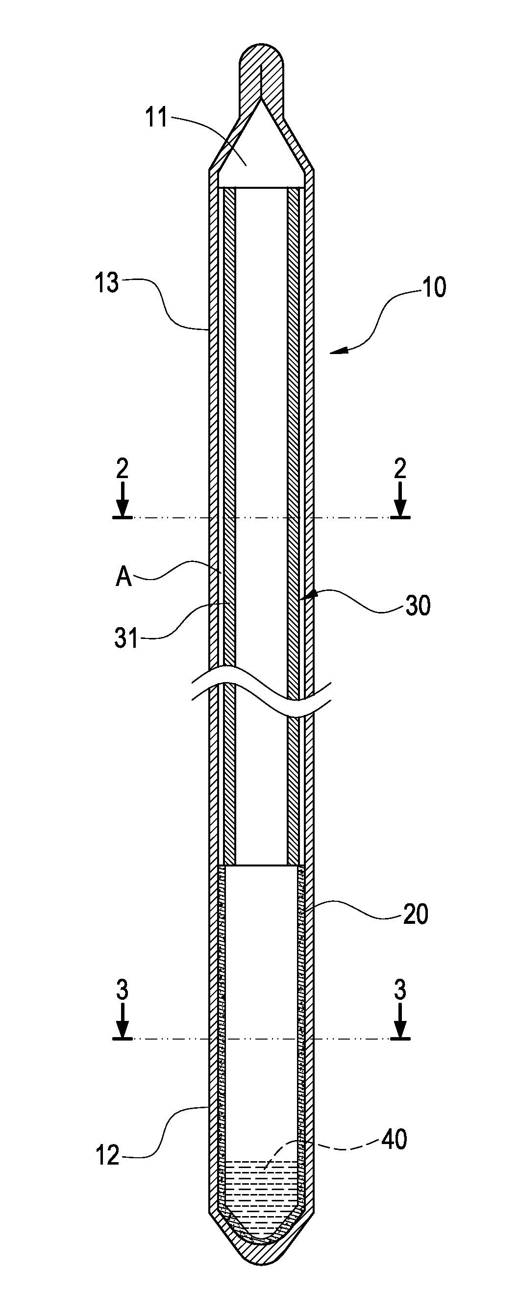
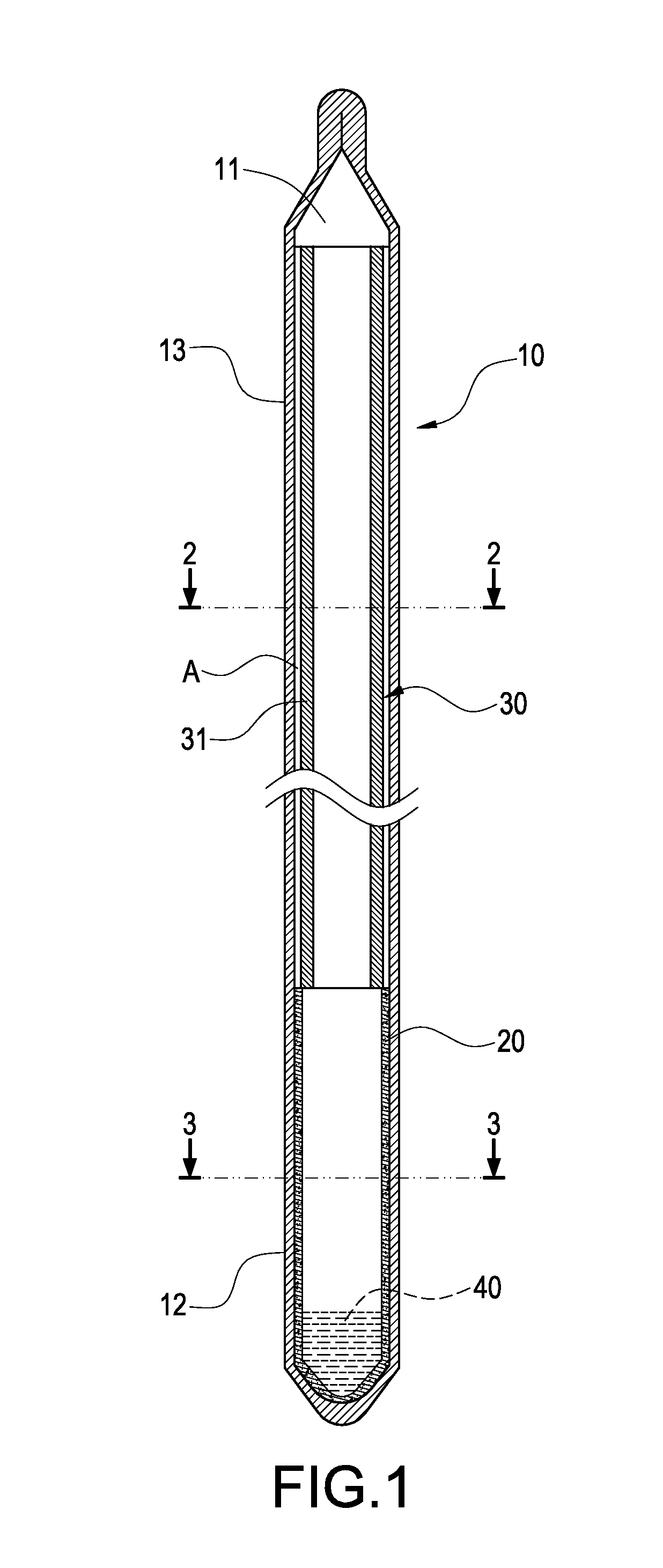
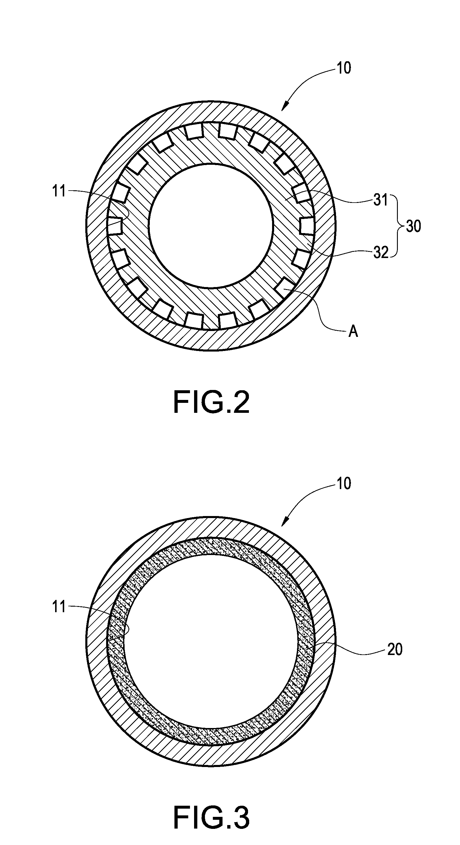
[0031]Referring to FIGS. 1 to 3 for a cross-sectional view of a heat pipe of the present, a cross-sectional view of Section 2-2 of FIG. 1 and a cross-sectional view of Section 3-3 of FIG. 1 respectively, the present invention provides a heat pipe with a dual capillary structure comprises a metal tube 10, a heat-absorption part 12, a heat-dissipation part 13, a first capillary 20, a second capillary 30 and a working fluid 40. The metal tube 10 includes a chamber 11 therein, the heat-absorption part 12 formed at the bottom section of the metal tube 10, and the heat-dissipation part 13 formed at the top section of the metal tube 10,...


PUM

PropertyMeasurementUnit
Capillary waveaaaaaaaaaa
Structureaaaaaaaaaa
Volumeaaaaaaaaaa

Abstract

A heat pipe with a dual capillary structure includes a metal tube, a first capillary, a second capillary and a working fluid. The metal tube forms a chamber and a heat-absorption part. The first capillary is formed by sintering a metal powder, and its corresponding heat-absorption part is disposed in the chamber and the second capillary is contained in the chamber and connected to an end of the first capillary. The second capillary includes an internal tube, a capillary tissue installed between inner walls of the internal tube and the metal tube, and a working fluid filled into the chamber. The invention further provides a method of manufacturing the heat pipe with a dual capillary structure.

Description

BACKGROUND OF THE INVENTION[0001]1. Field of the Invention[0002]The present invention generally relates to a heat pipe, and more particularly to a heat pipe with a dual capillary structure and a method of manufacturing the heat pipe.[0003]2. Description of Prior Art[0004]As the speed of a central processing unit (CPU) of a computer becomes increasingly higher, more heats are generated by a heat plate, and a traditional heat dissipating device composed of an aluminum extruded heat sink and a fan can no longer satisfy the requirements of present central processing units. Therefore, manufacturers continuously develop heat pipes with a high thermal conducting performance, and integrate the heat pipes with heat sinks to overcome the present heat dissipating issue. However, the structural design of the heat pipe and the quantity of a working fluid are related to the heat conducting speed and performance of the heat pipe. If the quantity of working fluid is too much and a gas channel in th...

Claims


Application Information

Patent Timeline
IPC IPC(8): F28D15/04F22B37/00B23P15/26
CPCB23P15/26B23P2700/09Y10T29/49353F28D15/046F28D15/0283
Inventor WANG, CHENG-TULIAO, PANG-HUNGTSENG, KUO-FENGLEE, CHUAN-YU
Owner CHAUN CHOUNG TECH
Features
  • Generate Ideas
  • Intellectual Property
  • Life Sciences
  • Materials
  • Tech Scout
  • Unparalleled Data Quality
  • Higher Quality Content
  • 60% Fewer Hallucinations
Learn More