Magnetic ranging and controlled earth borehole drilling

a controlled earth and magnetic field technology, applied in the direction of borehole/well accessories, instruments, surveys, etc., can solve the problems of time-consuming, inability to compute the distance to the first well, and introduce errors in the calculated distance between the two wells, so as to reduce the amount of rig time, reduce the strength of the magnetic field, and high and variable magnetic permeability

Inactive Publication Date: 2009-12-17
SCHLUMBERGER TECH CORP
View PDF6 Cites 55 Cited by
  • Summary
  • Abstract
  • Description
  • Claims
  • Application Information

AI Technical Summary

Benefits of technology

[0015]Among the advantages of the invention are the following: (1) A knowledge of the strength of the magnetic field sources is not required. This is important since the magnetic field sources may be located inside a steel casing which can have a high and variable magnetic permeability, which reduces the strength of the magnetic field outside the casing. Since the relative magnetic permeability of the casing is generally not known, this introduces an unknown variation in the magnetic field strength. However, the technique of the invention is not affected by the casing. (2) It is not necessary to move the downhole tool containing the two magnetic field sources during a measurement sequence. This reduces the amount of rig time required to make a magnetic ranging survey. (3) It is not necessary to actually know or to determine the position of the magnetometers (e.g. an MWD magnetometer device) with respect to the z direction. (4) Since the distance to the

Problems solved by technology

There are drawbacks to this process.
This movement requires that the tractor be activated and driven along the wellbore, which is time consuming.
Second, any errors in measuring the two axial positions of the solenoid, or errors in the distance the solenoid moves, introduce err

Method used


Image

  • Magnetic ranging and controlled earth borehole drilling
  • Magnetic ranging and controlled earth borehole drilling
  • Magnetic ranging and controlled earth borehole drilling

Examples


example # 1

EXAMPLE #1

SAGD Wells at 5 m Separation

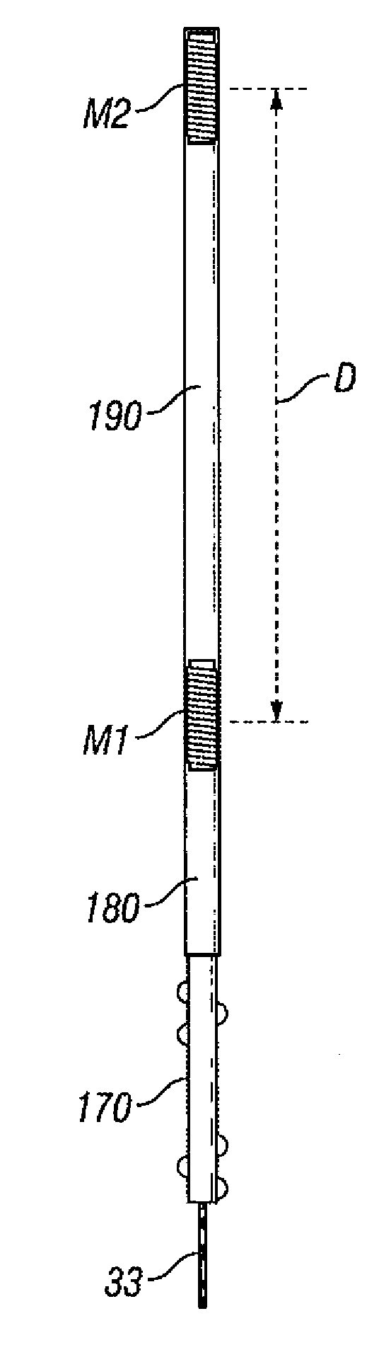
[0068]In this example, the two solenoids are separated by a distance d=10 m and each solenoid has a magnetic dipole moment of M=100 amp-meter2. A SAGD injector well is to be drilled 5 m above the producer well. It is assumed that the MWD magnetometer is located at (x3,y3,z3)=(5 m,1 m,z3), various quantities are plotted as a function of z3. The magnetic field components measured at the magnetometer (B1r, B1z, B2r, and B2z) are shown in FIG. 7. Noise with a standard deviation of 0.1 nTesla noise has been added to field components: B1x, B1y, B1z, B2x, B2y, and B2z. Note that the magnetic field is strongest over the range z3=−5 m to z3=+15 m. In FIGS. 8 to 11, the axial position of the MWD magnetometer (z3) is incremented in 1 m steps while inverting for r, x3, y3, and z3, respectively. The average results and standard deviations are also tabulated in Table 1 for two ranges: z3 ε[0.5 m,9.5 m] and z3 ε[−5.5 m,15.5 m]. The difference between the inver...

example # 2

EXAMPLE #2

SAGD Wells at 10 m Separation

[0069]In this example, the two solenoids are again separated by a distance d=10 m and each solenoid has a magnetic dipole moment of M=100 amp-meter2. A SAGD injector well is to be drilled 10 m above the producer well. It is assumed that the MWD magnetometer is located at (x3,y3,z3)=(10 m,1 m,z3), various quantities are plotted as a function of z3. The magnetic field components measured at the magnetometer are shown in FIG. 12. Noise with a standard deviation of 0.1 nTesla noise has been added to all field components. In FIGS. 13 to 16, the axial position of the MWD magnetometer (z3) is varied in 1 m steps while inverting for r, x3, y3, and z3, respectively. The average results and standard deviations are also tabulated in Table 2 for two ranges: z3 ε[0.5 m,9.5 m] and z3 ε[−5.5 m,15.5 m]. The results are still good for 0≦z3≦d, and still quite useful for −5≦z3≦d+5.

TABLE 2Inverted parameters for example #2. The average value and thestandard deviat...

example # 3

EXAMPLE #3

SAGD Wells at 15 m Separation

[0070]In this case, it is advantageous to separate the two solenoids to d=15 m and to increase the magnetic dipole moment to M=200 amp-meter2. It is assumed that the MWD magnetometer is located at (x3,y3,z3)=(15 m,1 m,z3), and various quantities are plotted as a function of z3. The magnetic field components measured at the magnetometer are shown in FIG. 17. Noise with a standard deviation of 0.1 nTesla noise has been added to all field components. In FIGS. 18 to 21, the axial position of the MWD magnetometer (z3) is varied in 1 m steps while inverting for r, x3, y3, and z3, respectively. The average results and standard deviations are also tabulated in Table 3 for two ranges: z3 ε[0.5 m,14.5 m] and z3 ε[−5.5 m,20.5 m]. The results provide an accuracy better than 1 m in all conditions, even with a potential uncertainty in z3 of ±13 m.

TABLE 3Inverted parameters for example #3. The average value and thestandard deviation are given for each range o...


PUM


Abstract

A method for determining the distance and/or direction of a second earth borehole with respect to a first earth borehole, includes the following steps: providing, in the first borehole, first and second spaced apart magnetic field sources; providing, in the second borehole, a magnetic field sensor subsystem for sensing directional magnetic field components; activating the first and second magnetic field sources, and producing respective first and second outputs of the magnetic field sensor subsystem, the first output being responsive to the magnetic field produced by the first magnetic field source, and the second output being responsive to the magnetic field produced by the second magnetic field source; and determining distance and/or direction of the second earth borehole with respect to the first earth borehole as a function of the first output and the second output.

Description

FIELD OF THE INVENTION[0001]This invention relates to systems and methods for magnetic ranging between earth boreholes, and for controlled drilling of an earth borehole in a determined spatial relationship with respect to another existing earth borehole.BACKGROUND OF THE INVENTION[0002]In the quest for hydrocarbons, the need can arise for drilling of an earth borehole in a determined spatial relationship with respect to another existing borehole. One example is the so-called steam-assisted gravity drainage (“SAGD”) process which is used to enhance production from an existing section of a generally horizontal production wellbore in a reservoir of high viscosity low-mobility crude oil. A second wellbore, to be used for steam injection, is drilled above and in alignment with the production wellbore. The injection of steam in the second wellbore causes heated oil to flow toward the production well, and can greatly increase recovery from the reservoir. However, for the technique to work ...

Claims


Application Information

Patent Timeline
IPC IPC(8): G01V3/08E21B25/16
CPCE21B47/02216E21B47/0228
Inventor CLARK, BRIANMORLEY, JAN S.
Owner SCHLUMBERGER TECH CORP
Why Eureka
Try Eureka