Displacement detecting method, correction table making method, motor control apparatus, and processing machine

a technology of displacement detection and correction table, applied in the direction of programme control, electrical controller, instruments, etc., can solve the problems of error, signal after correction is not ideal sine wave signal to be exact, and not ideal sine wave signal, etc., to achieve the effect of improving detection accuracy

Inactive Publication Date: 2009-12-17
CANON KK
View PDF8 Cites 12 Cited by
  • Summary
  • Abstract
  • Description
  • Claims
  • Application Information

AI Technical Summary

Benefits of technology

[0009]The present invention provides a displacement detecting method, a motor control apparatus, and a processing machine, which correct a detection error caused by a harmonic component contained in an encoder output signal or a process error of a scale pitch to improve detection accuracy.

Problems solved by technology

However, the encoder output signal contains a harmonic component and a nonlinear component, and it is not an ideal sine wave signal.
Therefore, even if the encoder output signal is corrected, the signal after the correction is not an ideal sine wave signal to be exact.
As a result, when performing the electric division, an error was caused.
Furthermore, a scale pitch of the encoder is processed so as to be arranged at equally-spaced intervals, but actually, a process error is generated.

Method used


Image

  • Displacement detecting method, correction table making method, motor control apparatus, and processing machine
  • Displacement detecting method, correction table making method, motor control apparatus, and processing machine
  • Displacement detecting method, correction table making method, motor control apparatus, and processing machine

Examples


embodiment 1

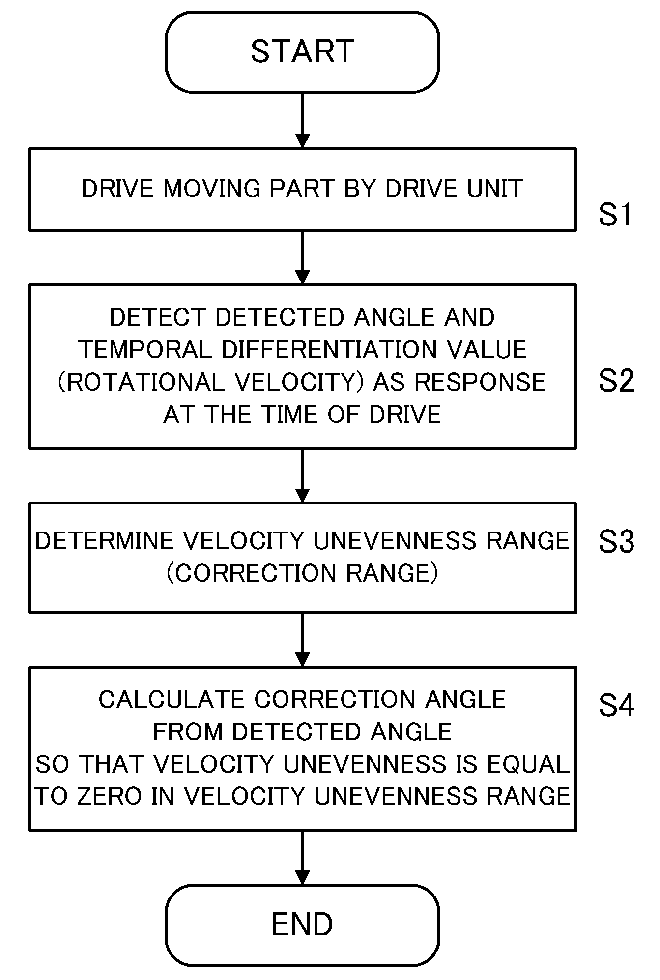
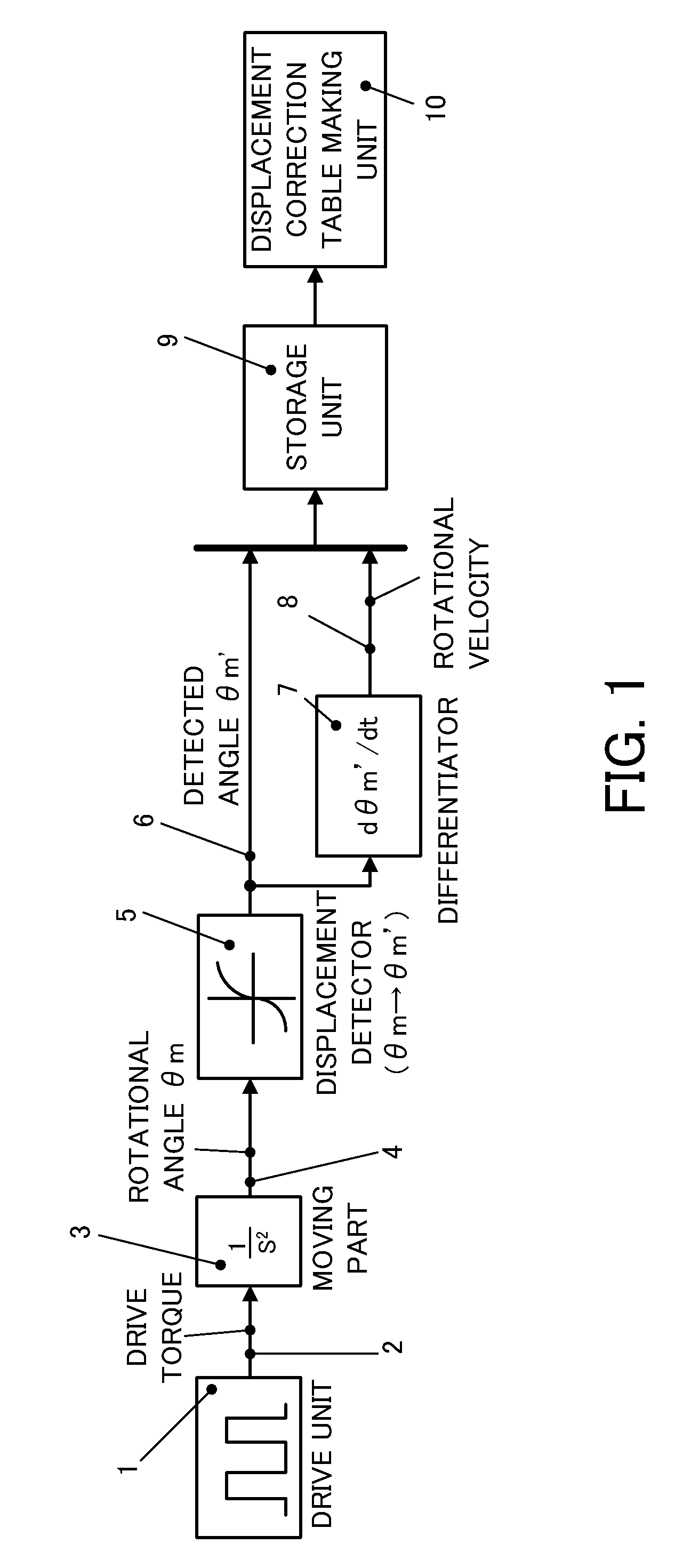
[0057]Next, a displacement detecting method and a motor control apparatus in embodiment 1 of the present invention will be described. FIG. 1 is a block diagram of a control which is performed by the motor control apparatus.

[0058]The control block in FIG. 1 is a positioning control system in which a rotary encoder is used as an angle detector for detecting a rotational angle θm of a motor. In FIG. 1, an easy model of a moving part in which position response with respect to a torque command is 1 / s2 is shown.

[0059]Reference numeral 1 denotes a drive unit (a drive torque generator). The drive unit 1 supplies a predetermined torque 2 to a moving part 3 (a rotary motor) based on an output signal from an upper controller (not shown). The moving part 3 of the present embodiment represents position response which has a transfer function of 1 / s2 with respect to the drive torque 2 (torque command) inputted from the drive unit 1.

[0060]The moving part 3 is displaced by a predetermined rotational...

embodiment 2

[0092]Next, embodiment 2 of the present invention will be described.

[0093]In the present embodiment, a model of a moving part where the position response for the torque command of the rotary motor is 1 / (s2+s+100) is considered. This model adds a model of a viscosity and a spring system to the model of embodiment 1. The model of the viscosity is reflected by “s” of the denominator in the above expression, and the model of the spring system is reflected by “100” of the denominator in the expression.

A Method for Correcting Angle Detection

[0094]First, a method for correcting angle detection in the present embodiment will be described.

[0095]Also in the present embodiment, the correction is performed by the same procedure as that of embodiment 1. First, similarly to embodiment 1, the waveform shown in FIG. 4 is applied as a torque. The time dependency of the detected angle θm′ and the rotational velocity (the temporal differentiation value) at this time is shown in FIG. 10. In FIG. 10, th...

embodiment 3

[0105]Next, embodiment 3 of the present invention will be described.

[0106]In the embodiment, the case where a process error in a scale pitch of an encoder is generated will be considered. Similarly to embodiments 1 and 2, a rotary motor is used as a moving part, and a rotary encoder (an angle detector) is used as a displacement detector. The encoder outputs a sine wave two-phase signal by 140000 periods per one rotation of a motor.

[0107]When the rotational angle of the motor is θm [rad], a phase angle θe [rad] of the encoder is represented by following expression (7).

θe=140000×θm  (7)

[0108]Two-phase sine wave signals Asig and Bsig of the encoder are represented by following expressions (8) and (9).

Asig=sin(θe+π2)(8)Bsig=sinθe(9)

[0109]However, when a process error in the scale pitch is generated, the relation of above expression (7) is not satisfied and a precise position can not be detected.

[0110]In the present embodiment, a detection correcting procedure in the case where a process...


PUM

PropertyMeasurementUnit
displacement detecting methodaaaaaaaaaa
displacement detectoraaaaaaaaaa
displacement correctionaaaaaaaaaa

Abstract

A displacement detecting method of the present invention includes the steps of driving a moving part 3 using a drive unit 1, detecting a displacement amount 6 (detected angle θm′) of the moving part 3 using a displacement detector 5, correcting the displacement amount 6 (detected angle θm′) using a displacement correction table so that a displacement velocity (dθm′/dt) of the displacement amount 6 (detected angle θm′) detected by the displacement detector 5 is constant, and detecting a displacement amount (detected angle θm″) corrected by the displacement correction table as the displacement amount of the moving part 3.

Description

BACKGROUND OF THE INVENTION[0001]1. Field of the Invention[0002]The present invention relates to a displacement detecting method, a correction table making method, a motor control apparatus, and a processing machine which correct displacement information to improve detection accuracy.[0003]2. Description of the Related Art[0004]The applicant is developing a galvano motor which is used for a processing machine such as a laser processing machine, a laser trimming machine, and a laser repair machine. An incremental encoder is adopted to the galvano motor as a highly accurate angle detector. The applicant is considering an electric dividing means of an encoder signal.[0005]Conventionally, the electric division was performed on the assumption that two-phase analog sine wave signal and cosine wave signal which have the same values of the amplitude and offset and have the phases differing by 90 degrees from each other are outputted. The electric division might be performed after correcting...

Claims


Application Information

Patent Timeline
Patent Type & Authority Applications(United States)
IPC IPC(8): G05B11/01G05B1/06G01B7/00H02P31/00B23K26/00G02B26/08H02P29/00
CPCB23K26/041B23K26/08B23K26/0807G05B19/408G01D5/24476G01D5/2448B23K26/20B23K26/082B23K26/042B23K26/21G01B7/00G01B11/00
Inventor UEDA, SHINJI
Owner CANON KK
Why Eureka
Try Eureka