Amr array magnetic design for improved sensor flexibility and improved air gap performance

an array magnetic and sensor technology, applied in the field of sensors, can solve the problems of decreasing the repeatability of signal changes, and achieve the effects of improving sensor flexibility, improving air gap performance, and improving sensor flexibility

Active Publication Date: 2009-12-17
HONEYWELL INT INC
View PDF5 Cites 9 Cited by
  • Summary
  • Abstract
  • Description
  • Claims
  • Application Information

AI Technical Summary

Benefits of technology

[0008]It is, therefore, one aspect of the present invention to provide for improved sensor methods and systems.
[0009]It is another aspect of the present invention to provide an improved AMR position sensing system.
[0010]It is a further aspect of the present invention to provide an improved AMR array magnetic position sensing system for improved sensor flexibility and improved air gap performance.
[0011]The aforementioned aspects and other objectives and advantages can now be achieved as described herein. An AMR array magnetic position sensing system for improved sensor flexibility and improved air gap performance is disclosed. A pair of magnets can be enclosed in a magnet carrier that moves along a path and located above an array of AMR position sensors. The magnets are generally magnetized through the length of the magnets. The AMR position sensors can come into contact with the uniform magnetic flux lines to sense a change in linear and angular position associated with the magnet carrier. The output signal generated by the AMR position sensors have less susceptibility to variations in air gap as the angles of the magnetic flux lines generated by the magnets are not changing with air gap variation.
[0012]The AMR position sensors can be located external to the two magnets, such that the sensor comes into contact with the uniform magnetic flux lines to sense a change in angular and linear position associated with the rotatable base. The AMR array position sensors can sense linear and rotary position of the magnets while the magnet carrier is moving in the linear or rotary magnetized direction to efficiently sense the position of the moving magnet carrier. Such an AMR array magnetic sensor design can improve the performance of the AMR array sensors with respect to changes of air gap.

Problems solved by technology

The problem associated with such prior art position sensing system 100 is that as the distance between the AMR position sensors 130 and the magnet 110 changes, the signal changes decreasing repeatability of the sensor.

Method used


Image

  • Amr array magnetic design for improved sensor flexibility and improved air gap performance
  • Amr array magnetic design for improved sensor flexibility and improved air gap performance
  • Amr array magnetic design for improved sensor flexibility and improved air gap performance

Examples


Embodiment Construction

[0022]The particular values and configurations discussed in these non-limiting examples can be varied and are cited merely to illustrate at least one embodiment and are not intended to limit the scope thereof.

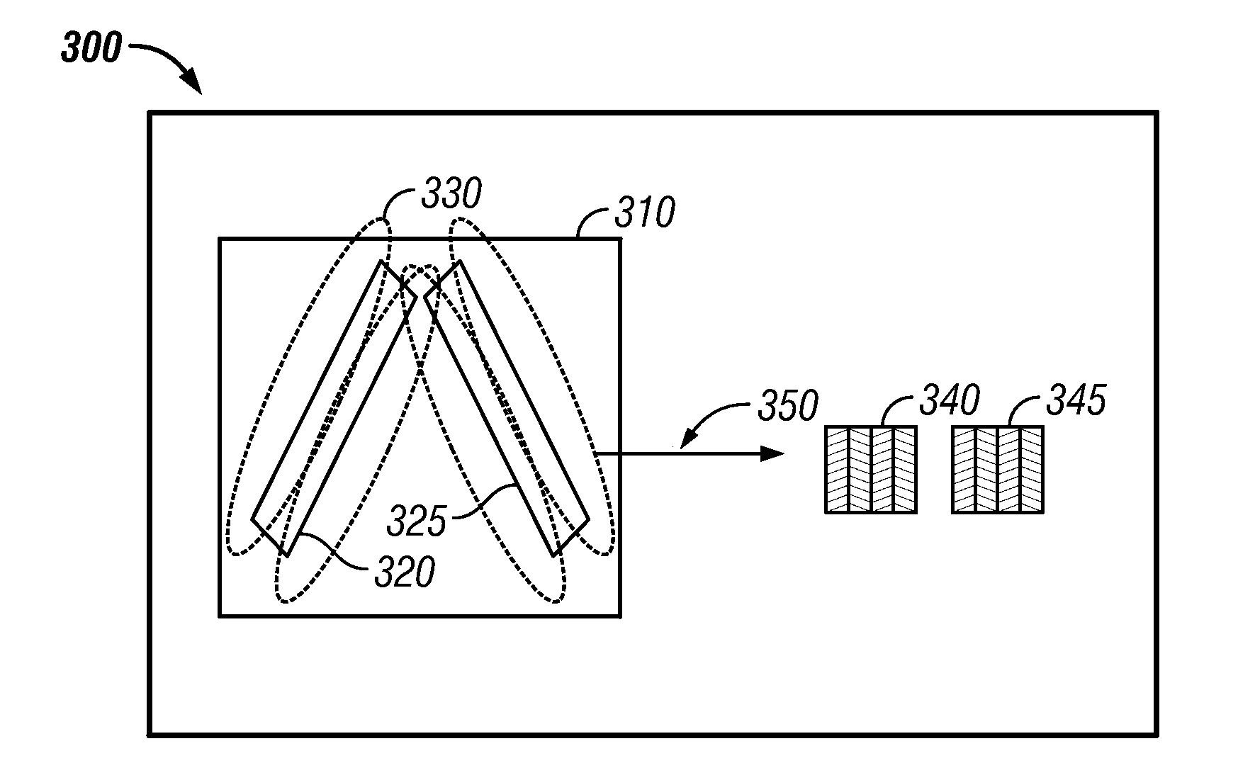
[0023]FIG. 3 illustrates a perspective view of an AMR position sensing system 300, in accordance with a preferred embodiment. The AMR position sensing system 300 generally includes a magnet carrier 310, which holds two magnets 320 and 325. The magnets 320 and 325 are generally magnetized through the length of the magnets to create uniform magnetic flux lines 330 thereof. The AMR position sensing system 300 also includes an array of AMR position sensors 340 with AMR runners 345 located respectively external to first and second magnets 320 and 325. The magnets 320 and 325 enclosed in the magnet carrier 310 moves along a path 350 and generally located centrally above the array of AMR position sensors 340. Note that as utilized herein, the term “above” can refer to both vertical an...


PUM


Abstract

An AMR array magnetic position sensing system for improved sensor flexibility and improved air gap performance is disclosed. A pair of magnets can be enclosed in a magnet carrier that moves along a path and located above an array of AMR position sensors. The magnets are generally magnetized through the length of the magnets, and the magnets are positioned in the carrier such that an angle between the magnets exists in a manner similar to an angle made by AMR runners on a surface of the AMR positions sensors to create magnetic flux lines thereof. The AMR position sensors come into contact with the uniform magnetic flux lines to sense a change in linear and angular position associated with the magnet carrier. The output signal generated by the AMR position sensors have less susceptibility to variations in air gap as the angles of the magnetic flux lines generated by the magnets do note change with respect to air gap variation.

Description

TECHNICAL FIELD[0001]Embodiments are generally related to sensor methods and systems. Embodiments are also related to magnetic sensors. Embodiments are additionally related to Anisotropic Magnetoresistive (AMR) array magnetic designs for improved sensor flexibility and improved air gap performance.BACKGROUND OF THE INVENTION[0002]Magnetoresistive (MR) technology can be utilized in a variety of commercial, consumer, and industrial detection applications. Anisotropic Magnetoresistance (AMR) is the property of a material in which the electrical resistance can change depending on the angle between the direction of electrical current and orientation of magnetic field is observed. AMR array position sensors yield a very accurate signal with respect to the position of a magnet. In conventional MR systems, for example, a device may be provided for determining the position of a member movable along a path. The device includes a magnet attached to the movable member and an array of AMR sensor...

Claims


Application Information

Patent Timeline
Patent Type & Authority Applications(United States)
IPC IPC(8): G01R33/02
CPCG01R33/1215G01R33/09G01D5/145G01D5/24438
Inventor DMYTRIW, ANTHONYVAN OSTRAND, KENT E.
Owner HONEYWELL INT INC
Why Eureka
Try Eureka