
Predistortion Apparatus, System, And Method

a predistortion apparatus and predistors technology, applied in the field of radio transmitters, can solve the problems of huge computational amount, unsteady envelope of modulation signals, and very high demands on the linearity of the power amplifier inside the transmitter

Inactive Publication Date: 2009-12-17
FUJITSU LTD
View PDF8 Cites 6 Cited by
  • Summary
  • Abstract
  • Description
  • Claims
  • Application Information

AI Technical Summary

Benefits of technology

[0019]Different from prior art methods, the apparatus and method according to the present invention need not perform interpolation operation to calculate the contents of the lookup tables, and are therefore relatively low in computational complexity. The predistorter according to the present invention as synthesized based on the orthogonal lookup tables has great degree of freedom and excellent flexibility. At the same time, the orthogonal lookup tables obtained in the present invention are irrelevant to statistical characteristics of input signals. Moreover, tendency and scope of changes of the predistortion parameters can be controlled by priori knowledge of changes in the power amplification characteristics with temperature and time.

Problems solved by technology

These modulation signals have unsteady envelopes that put very high demands on linearity of the power amplifier inside the transmitter.
One essential problem in the algorithm rests in using what kind of structure and algorithm to realize the lookup table predistorter as well as update of the predistortion lookup tables used therein.
With regard to this method, when there are many items in the lookup table, interpolation operation leads to huge computational amount, which is difficult for real-time implementation.
Although this method requires few predistortion parameters, the predistortion table obtained thereby has relatively low degree of freedom and inferior flexibility.
These methods also have inferior flexibility while requiring more storage capacity.

Method used


Image

  • Predistortion Apparatus, System, And Method
  • Predistortion Apparatus, System, And Method
  • Predistortion Apparatus, System, And Method

Examples


Embodiment Construction

[0028]The present invention is described in greater detail below with reference to the accompanying drawings. For the sake of clarity and brevity, descriptions of prior art component parts that may cause unclarities to the present invention are omitted. In addition, identical or similar component parts in the present invention are described with the help of the same reference numerals, and repetitive descriptions thereof are omitted.

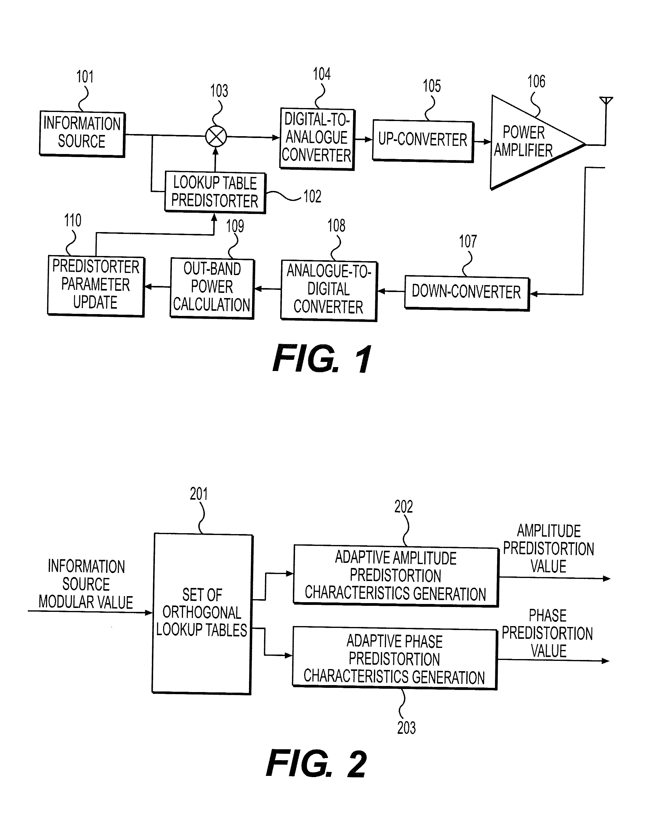
[0029]First of all, the present invention provides a predistorter that can be used to replace the lookup table predistorter 102 as shown in FIG. 1.

[0030]FIG. 2 is a schematic view illustrating the principles of the predistorter according to one embodiment of the present invention. As shown in FIG. 2, the present invention uses a set of lookup tables 201 orthogonal to one another. This set of lookup tables does not have to be updated, and serves as bases for amplitude predistortion and phase predistortion. Modular value detection is performed on an inform...


PUM


Abstract

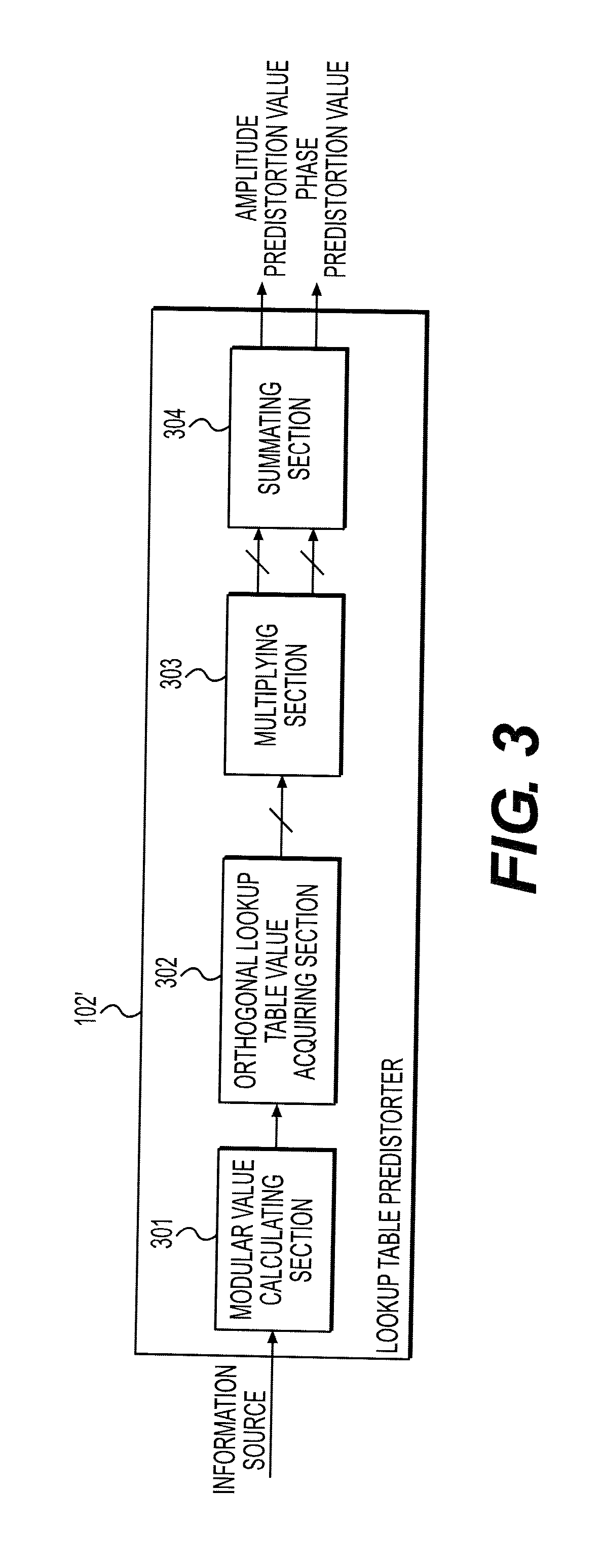
The present invention discloses a predistortion apparatus, a predistortion system and a predistortion method. The predistorter comprises a modular value calculating section, for performing modular arithmetic on an information source input signal inputted from an information source; an orthogonal lookup table value acquiring section, for searching N stored lookup tables orthogonal to one another, finding out corresponding output of each lookup table in accordance with the modular value of the information source input signal, and acquiring N lookup table values, wherein N is an integer greater than 1; a multiplying section, for multiplying the N lookup table values acquired by the orthogonal lookup table value acquiring section with N amplitude adjustment factors to obtain N amplitude adjustment values, and multiplying the N lookup table values with N phase adjustment factors to obtain N phase adjustment values; and a summating section, for summating the N amplitude adjustment values to obtain an amplitude predistortion value, and summating the N phase adjustment values to obtain a phase predistortion value.

Description

FIELD OF THE INVENTION[0001]The present invention relates to radio transmitters, and more precisely to RF power amplification in a transmitter.BACKGROUND OF THE INVENTION[0002]With the development of communications system, various modulation modes of high frequency spectrum efficiency are widely used. These modulation signals have unsteady envelopes that put very high demands on linearity of the power amplifier inside the transmitter. The method of linearization therefore becomes an indispensable technique. Due to its simplicity, flexibility and low cost, digital baseband predistortion has become an effective method of power amplification linearization.[0003]Predistortion method employing scalar information (such as the out-band power and in-band / out-band power ratios of a power-amplified output signal) as the optimization objective can avoid influences of such factors as the delay of the feedback loop and I / O unbalancing, and is more simple and effective.[0004]FIG. 1 is a block dia...

Claims


Application Information

Patent Timeline
IPC IPC(8): H03F1/26
CPCH03F2201/3233H03F1/3247
Inventor LI, HUISHI, ZHANZHOU, JIANMIN
Owner FUJITSU LTD
Learn More