Electronic Device

Inactive Publication Date: 2009-12-17
KYOCERA CORP
View PDF6 Cites 21 Cited by
  • Summary
  • Abstract
  • Description
  • Claims
  • Application Information

AI Technical Summary

Benefits of technology

[0019]According to the present invention, the portion of the battery holding portion formed facing the mount surface of the circuit board which faces the circuit board is constituted by a heat conduction member having a higher heat conductivity in comparison with the other portions, there

Problems solved by technology

However, TV tuner modules generate a considerable amount of heat during operation.
However, in portable devices, use of these structures was diff

Method used


Image

  • Electronic Device
  • Electronic Device
  • Electronic Device

Examples


Embodiment Construction

[0028]Below, an embodiment of the present invention will be explained.

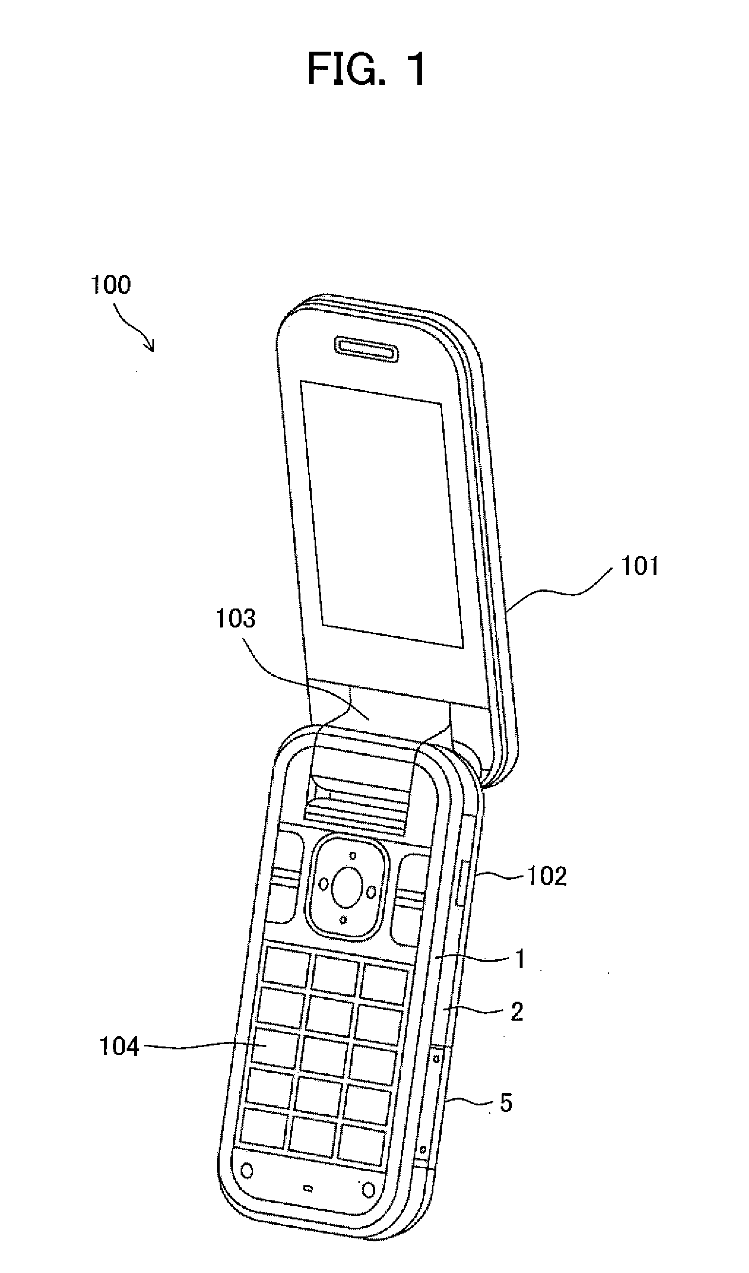
[0029]FIG. 1 is a diagram showing an outer appearance of a mobile phone 100 of the present embodiment.

[0030]As shown in FIG. 1, the mobile phone 100 is constituted by an upper case 101 and a lower case 102.

[0031]The upper case 101 and the lower case 102 are constituted so that these can be opened / closed by a hinge portion 103.

[0032]The upper case 101 has a liquid crystal screen or other display portion.

[0033]The lower case 102 holds a circuit board on which electronic components generating heat at the time of operation are mounted.

[0034]Below, the lower case 102 will be explained in detail.

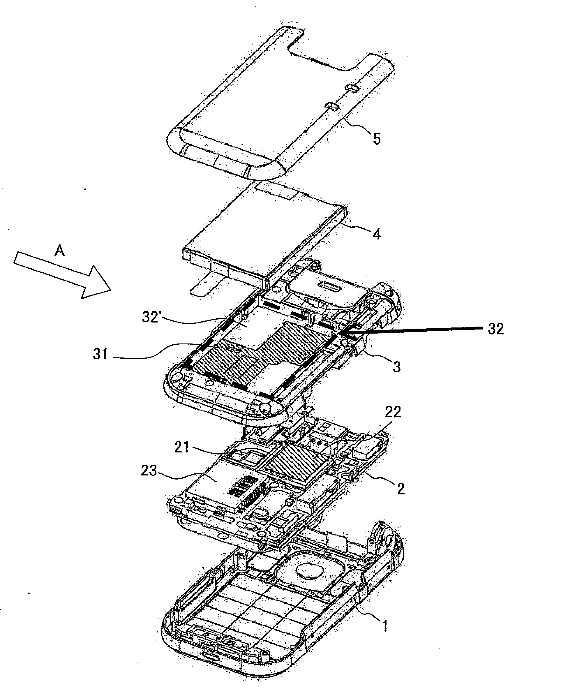
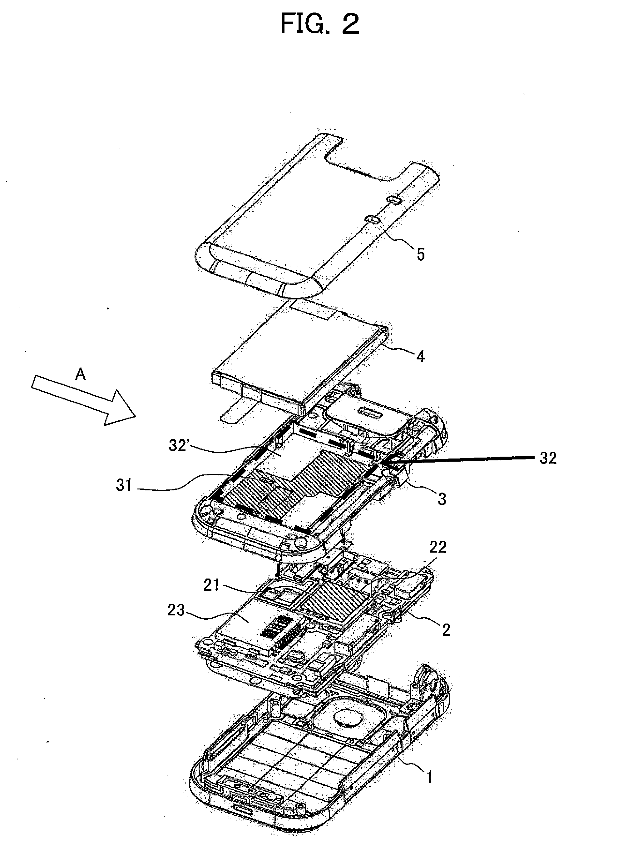
[0035]The lower case 102, as shown in FIG. 1 and FIG. 2, has a key front case 1 in which ten-keys and other key buttons 104 are provided, a circuit board 2, a key rear case 3 connected to the key front case 1, a battery 4 as a power supply of the mobile phone 100, and a battery lid 5. These are disposed in a thickness direction ...


PUM


Abstract

An electronic device able to stably disperse heat generated by an electronic component is provided. By providing a heat dissipating metal plate 31 having a high heat conductivity between a TV tuner 21 and a battery 4, heat generated by the TV tuner 21 is dispersed to the battery 4 having a large heat capacity and further dissipated to the outside of a case through a battery lid 5.

Description

TECHNICAL FIELD[0001]The present invention relates to an electronic device including an electronic component generating heat.BACKGROUND ART[0002]Recently, electronic devices arranges electronic components by high density and increased in amount of heat generated along with their reduction in size and improvement in performance. In particular, in mobile phones, since Apr. 1, 2006, broadcasting services for portable electronic devices have formally started in Japan by the IDSB-T (Integrated service Digital Broadcasting-Terrestrial). It is anticipated that electronic devices mounting TV tuners will increase from now on.[0003]However, TV tuner modules generate a considerable amount of heat during operation. In order to mount electronic components generating heat in this way in small cases such as mobile phones and other portable electronic devices, sufficient countermeasures against heat are necessary.[0004]Conventionally, the following measures have been used to dissipate the heat of e...

Claims


Application Information

Patent Timeline
IPC IPC(8): H05K7/20
CPCH04B1/036H05K7/20445H04M1/0262H04B1/40
Inventor KONDOH, YOSHIAKIYAHAGI, HIROTO
Owner KYOCERA CORP
Why Eureka
Try Eureka