Image forming apparatus and control method therefor

a technology of image forming apparatus and control method, which is applied in the direction of electrographic process apparatus, instruments, corona discharge, etc., can solve the problems of reducing the development ability, affecting image quality, and prone to image defects, so as to reduce the occurrence of image defects, maintain the density constant, and improve the development ability

Active Publication Date: 2009-12-17
CANON KK
View PDF10 Cites 7 Cited by
  • Summary
  • Abstract
  • Description
  • Claims
  • Application Information

AI Technical Summary

Benefits of technology

[0015]The present invention provides an image forming apparatus and a control method therefor, which are capable of suppressing occurrences of image defects and maintaining the image density constant while improving the development ability.

Problems solved by technology

However, the prior art entails the following problems.
The development ability is improved by a narrow S-D gap, but image defects are liable to occur when the S-D gap is narrow, as with a case where the AC bias voltage is excessively large.
On the other hand, a wide S-D gap results in a reduction in development ability.
With a variation in diameter of the stop rollers or a variation in dimension of the spacer, the S-D gap varies between image forming apparatuses, which poses a problem.
At that sleeve part, there occurs abnormal discharge causing a problem that ring-like spots are formed on the image and the resultant image quality is largely impaired.
When the S-D gap is wide, on the other hand, a problem is posed that the development ability is lowered as described above.
When the S-D gap dynamically varies, the image density becomes low at a part where the S-D gap is wide and becomes high at a part where the S-D gap is narrow, resulting in undesired bands of light and shade appearing on the image.

Method used


Image

  • Image forming apparatus and control method therefor
  • Image forming apparatus and control method therefor
  • Image forming apparatus and control method therefor

Examples


first embodiment

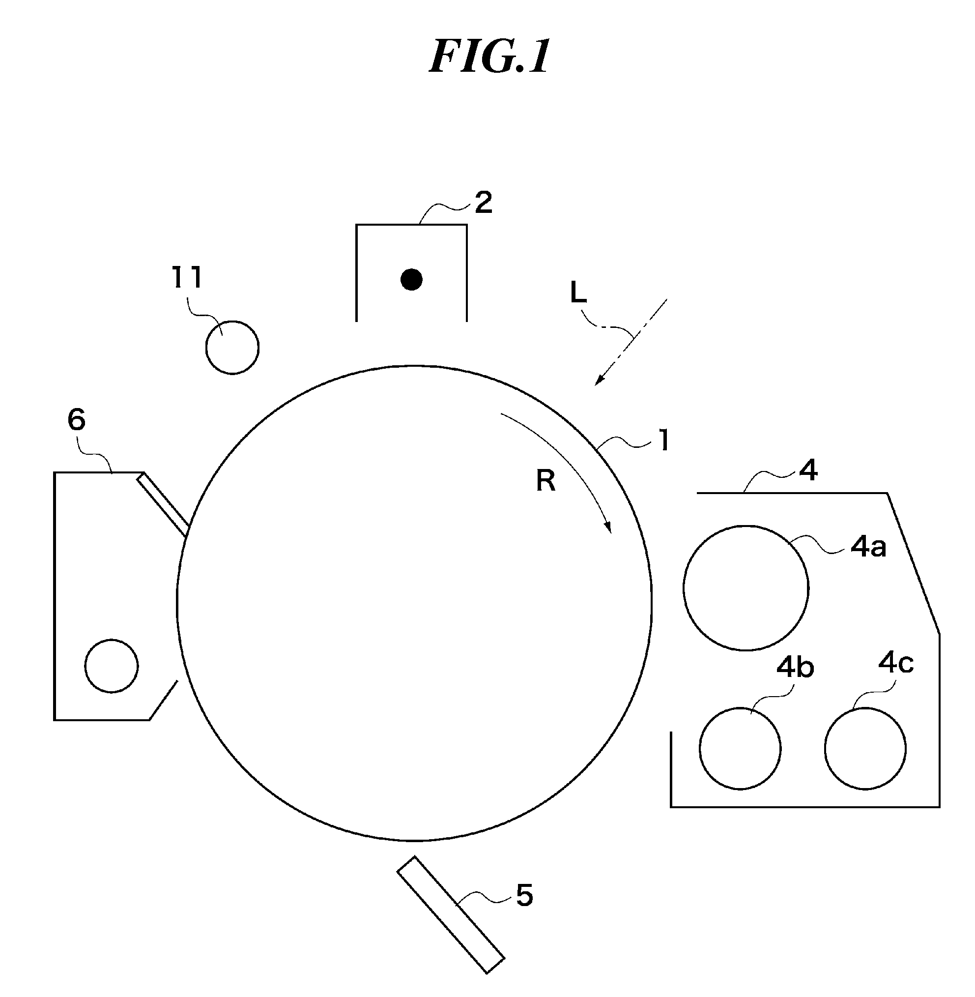
[0042]FIG. 1 shows the construction of and around a photosensitive drum and a developing device of an image forming apparatus according to a first embodiment of this invention.

[0043]As shown in FIG. 1, the image forming apparatus includes a photosensitive drum 1 around which a primary charger 2, a developing device 4, a transfer charger 5, a cleaner 6, and a preexposure device 11 are disposed. The image forming apparatus performs electrophotographic image formation in which an electrostatic latent image formed on the photosensitive drum 1 is developed into a toner image, which is then transferred onto a sheet. The photosensitive drum 1 is an image carrier carrying thereon an electrostatic latent image and rotatably driven by a drive mechanism (not shown) in a direction of arrow R. In a charging process, the photosensitive drum 1 is uniformly charged at its surface by the primary charger 2. In an exposure process, the surface of the photosensitive drum 1 is exposed to laser light L e...

second embodiment

[0076]A second embodiment of this invention is different from the first embodiment in that the developing AC-bias voltage is not set in accordance with an instruction from the CPU on the control circuit board, but is set by means of feedback control by the developing high-voltage circuit board. In other respects, this embodiment is the same as the first embodiment (FIGS. 1 and 2) and hence a duplicative description will be omitted.

[0077]FIG. 7 shows in block diagram the construction of a developing high-voltage circuit board and a control circuit board of an image forming apparatus of this embodiment. FIG. 8 shows in block diagram the detailed construction of the AC high-voltage drive circuit in FIG. 7. It should be noted that the construction in FIG. 7 is an example of the application unit, the detection unit, and the control unit of this invention.

[0078]As shown in FIGS. 7 and 8, the image forming apparatus includes a developing high-voltage circuit board 700 and a control circuit...

third embodiment

[0085]A third embodiment of this invention is different from the first embodiment in that the Vp-p set value of the developing AC-bias voltage is changed by a user or a service personnel by operating an operation unit. In other respects, this embodiment is the same as the first embodiment (FIGS. 1 and 2), and hence a duplicative description will be omitted.

[0086]FIG. 9 shows in block diagram the construction of a developing high-voltage circuit board and a control circuit board of an image forming apparatus of this embodiment. It should be noted that the arrangement shown in FIG. 9 is an example of the application unit, detection unit, control unit, display unit, and setting unit of this invention.

[0087]As shown in FIG. 9, the image forming apparatus includes a developing high-voltage circuit board 900 and a control circuit board 905. The developing high-voltage circuit board 900 is mounted with an AC high-voltage drive circuit 901 (application unit), an AC transformer 902, a DC hig...


PUM


Abstract

An image forming apparatus capable of suppressing occurrences of image defects and maintaining the image density constant while improving the development ability. The image forming apparatus includes a photosensitive drum on which an electrostatic latent image is carried, a developing sleeve on which developer is carried, an AC high-voltage drive circuit, an AC transformer, a DC high-voltage circuit, a p-p voltage detection circuit, and a CPU. The p-p voltage detection circuit converts a peak-to-peak voltage across a capacitor into a DC voltage which is taken out as a capacity detection signal. Based on the capacity detection signal output from the p-p voltage detection circuit, the CPU changes an image formation condition, e.g., a set value of a developing bias voltage.

Description

BACKGROUND OF THE INVENTION[0001]1. Field of the Invention[0002]The present invention relates to an image forming apparatus for forming an image by development, and relates to a control method for the image forming apparatus.[0003]2. Description of the Related Art[0004]In a conventional image forming apparatus for electrophotographic or electrostatic image formation, development is performed generally by using an image carrier (photosensitive drum) carrying thereon an electrostatic latent image and a developer carrier (developing sleeve) carrying a developer on it. At the time of development, a developing bias voltage is applied to the developing sleeve to generate an electric field between the sleeve and the photosensitive drum.[0005]As the developing bias voltage, there is used for example a voltage having a DC (direct current) component on which an AC (alternating current) component is superimposed as shown in FIG. 18. Specifically, the bias voltage in FIG. 18 (referred to as the...

Claims


Application Information

Patent Timeline
Patent Type & Authority Applications(United States)
IPC IPC(8): G03G15/00G03G15/06G03G15/02G03G15/043
CPCG03G2215/0634G03G15/065
Inventor TAMAOKI, TOMOHIRO
Owner CANON KK
Why Eureka
Try Eureka