Battery electrode sheet

a battery electrode and electrode technology, applied in the field of lithium ion battery cells and systems, can solve the problems of increasing public awareness of cost and environmental issues, deficient battery systems for use with electric motors employed in pure electric and hybrid vehicles, and inability to meet the needs of electric motors,

Active Publication Date: 2009-12-17
BYD CO LTD
View PDF24 Cites 54 Cited by
  • Summary
  • Abstract
  • Description
  • Claims
  • Application Information

AI Technical Summary

Benefits of technology

[0033]In one aspect, a battery electrode sheet comprises a conductive substrate; and an electrode material coated on at least a portion of the conductive substrate. The coated portion of the conductive substrate comprises a first region, a second region, and a transition region between the first and second regions. The electrode material on the first region has a first thickness; and the electrode material on the second region has a second thickness, which is smaller than the first thickness. The electrode material on the transition region has a thickness that decreases between the first and second regions.
[0034]In another aspect, a method for preparing a battery electrode sheet comprises: coating an electrode material onto at least a portion of a conductive substrate. The coated portion of the conductive substrate comprises a first region, a second region, and a transition region between the first and second regions. The electrode material on the first region has a first...

Problems solved by technology

The public has become increasingly sensitive to cost and environmental issues associated with the use of fossil-based fuels.
Battery systems for use with electric motors employed in pure electric and hybrid vehicles are currently deficient in many respects.
Individual battery cells of the battery system are frequently heavy, bulky, and unreliable.
Further, current battery cells are neither constructed nor used to effectively provide the high power output needed to accelerate the vehicle at an acceptable ...

Method used


Image

  • Battery electrode sheet
  • Battery electrode sheet
  • Battery electrode sheet

Examples


first embodiment

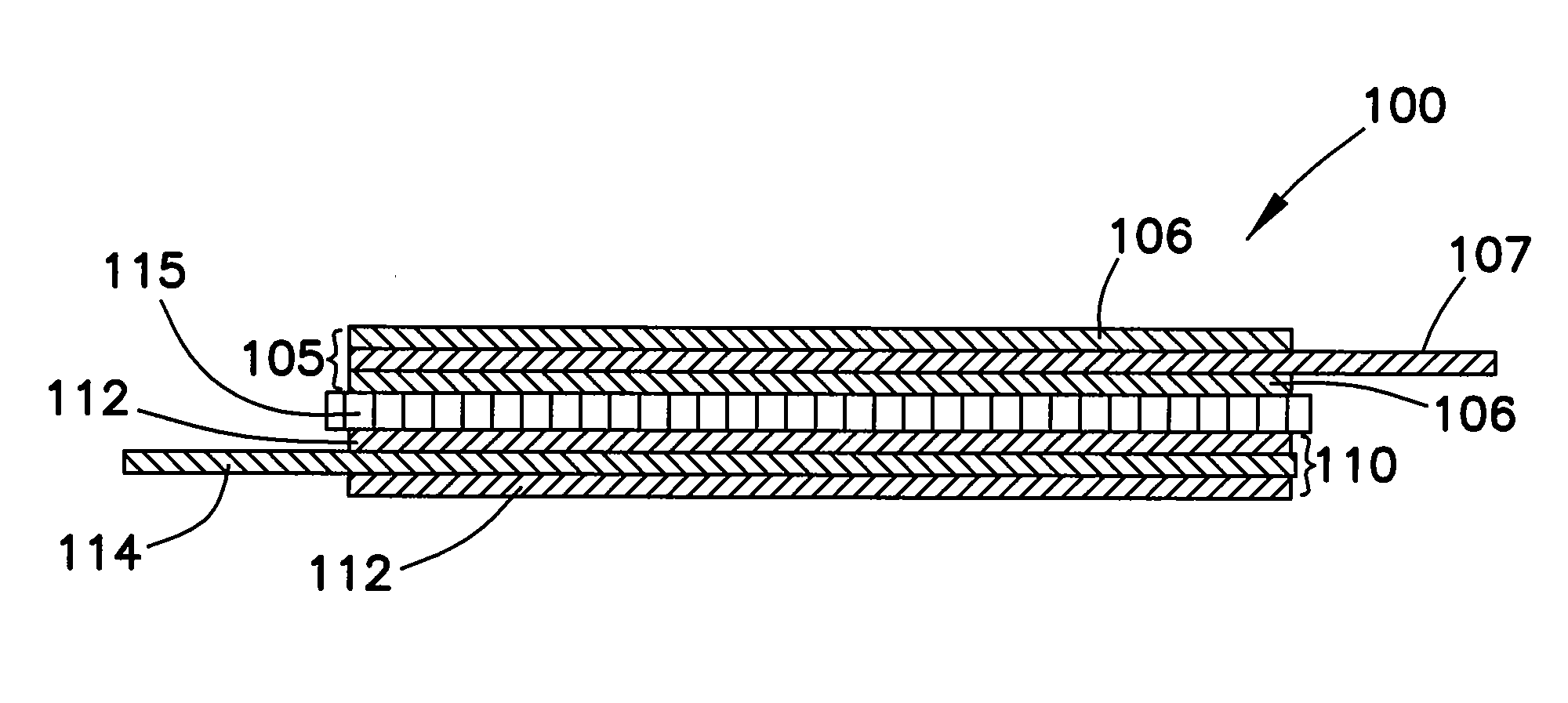
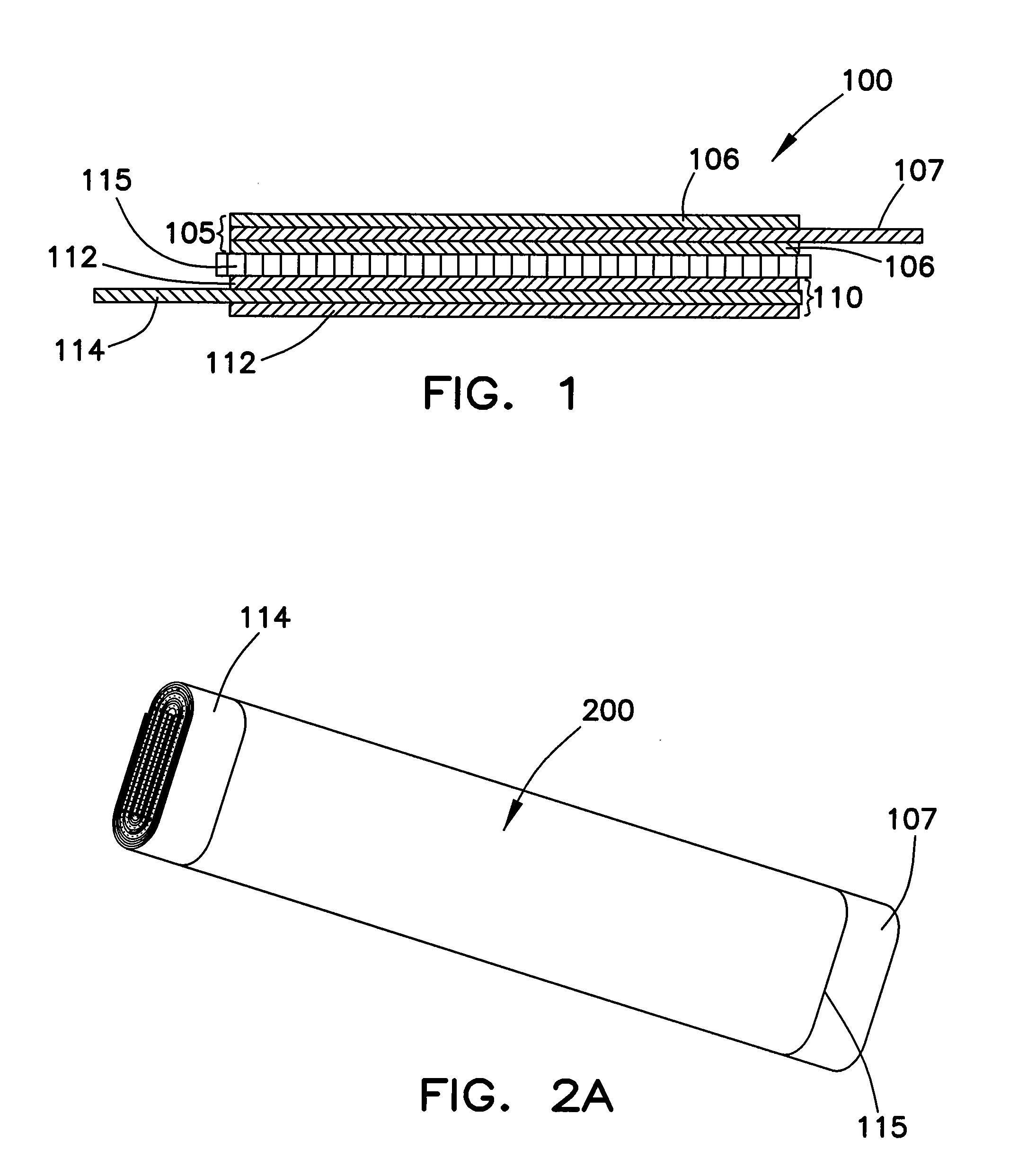
[0256]The first embodiment explains a battery electrode sheet and a battery of the present disclosure.

[0257]A cathode material, a conductive agent, an adhesive agent and a solvent were mixed and stirred to prepare a cathode slurry.

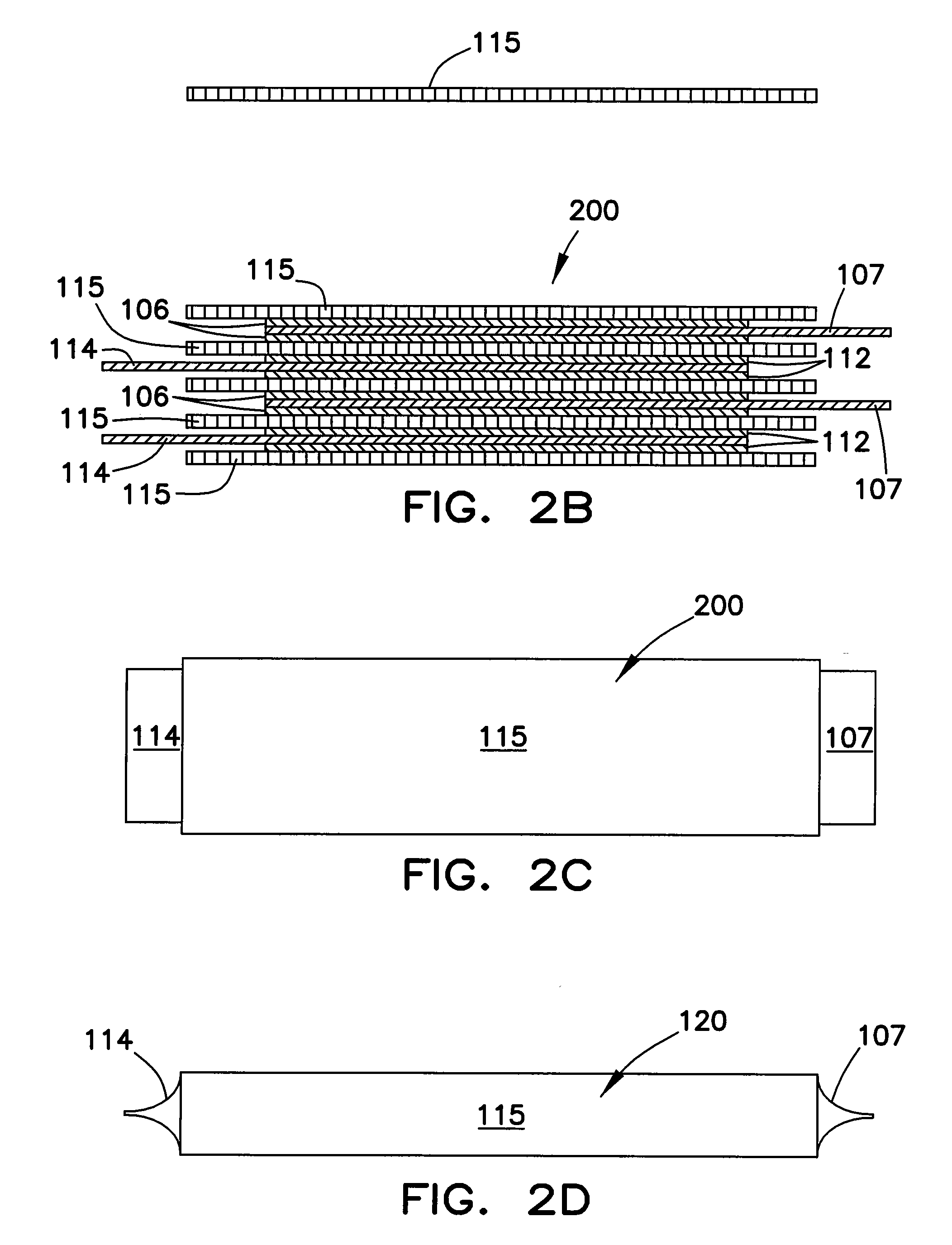
[0258]A first region, a transition region, a second region, and an exposed region were assigned on a current collector. The transition region had a width of about 4 mm. The second region had a width of about 4 mm. The exposed region had a thickness of about 30 mm. The slurry was coated uniformly on the first region and the transition region at a thickness of about 100 μm. The cathode slurry on the transition region was thinned using a machine blade. The transition region had the slurry with a maximum thickness of about 100 μm, a minimum thickness of about 25 μm, and a descending gradient of about 18.75 μm / mm. Then the slurry was coated on the second region. The cathode slurry on the second region was about 25 μm.

[0259]The coated current collector was then ...

second embodiment

[0264]The second embodiment is used to explain a battery electrode sheet and a battery of the present disclosure.

[0265]The method was the same as described in the first embodiment. The only difference was that: before coiling, a polyphenylene sulfide tape having a thickness of about 80 μm was applied onto the transition region and the second region. The obtained cathode sheets were denoted as A21. The obtained batteries were denoted as A2.

third embodiment

[0266]The third embodiment explains a battery electrode sheet and a battery using of the present disclosure.

[0267]A cathode material, a conductive agent, an adhesive agent and a solvent were mixed and stirred to provide a cathode slurry.

[0268]A first region, a transition region, a second region, and an exposed region were assigned on a current collector. The transition region had a width of about 6 mm. The second region had a width of about 6 mm. The tab region had a width of about 50 mm. The cathode slurry was coated uniformly on the first region and the transition region. The cathode slurry had a thickness of about 90 μm. The cathode slurry on the transition region was thinned gradually by a machine blade. The transition region had the cathode slurry with a maximum thickness of about 90 μm, a minimum thickness of about 30 μm, and a descending gradient of about 10 μm / mm. Then the slurry was coated on the second region at a thickness of about 30 μm.

[0269]The coated current collector...


PUM


Abstract

A battery electrode sheet comprises a conductive substrate and an electrode material coated on at least a portion of the conductive substrate. The coated portion of the conductive substrate comprises a first region, a second region, and a transition region between the first and second regions. The electrode material on the first region has a first thickness; and the electrode material on the second region has a second thickness, which is smaller than the first thickness. The electrode material on the transition region has a thickness that decreases between the first and second regions.

Description

RELATED U.S. APPLICATION DATA[0001]Continuation-in-part of application Ser. No. 12 / 341,787, filed on Dec. 22, 2008.PRIORITY CLAIM[0002]The present application claims priority to the following Patent Applications, which are hereby incorporated by reference:[0003]Application Number 100720196395.2, filed Dec. 25, 2007;[0004]Application Number 200820116496.9, filed Jun. 30, 2008;[0005]Application Number 200810145734.3, filed Aug. 14, 2008;[0006]Application Number 200810135478, filed Aug. 7, 2008;[0007]Application Number 200810135477.5, filed Aug. 7, 2008;[0008]Application Number 200810142082.8, filed Aug. 27, 2008;[0009]Application Number 200810142090.2, filed Aug. 27, 2008;[0010]Application Number 200810142083.2, filed Aug. 27, 2008;[0011]Application Number 200820146848.5, filed Aug. 27, 2008;[0012]Application Number 200820146851.7, filed Aug. 27, 2008;[0013]Application Number 200820146849, filed Aug. 27, 2008;[0014]Application Number 200810142084.7, filed Aug. 27, 2008;[0015]Applicati...

Claims


Application Information

Patent Timeline
IPC IPC(8): H01M4/02B05D5/12H01M2/14H01M10/36H01M50/147H01M50/176H01M50/184H01M50/186H01M50/417H01M50/469H01M50/503H01M50/516
CPCH01M2/04Y02T10/7011H01M2/08H01M2/1094H01M2/1241H01M2/1653H01M2/1673H01M2/18H01M2/202H01M2/22H01M2/347H01M4/0404H01M4/043H01M4/13H01M4/139H01M4/62H01M10/0525H01M10/0587H01M10/486H01M10/5004H01M10/5006H01M10/5016H01M10/5032H01M10/504H01M10/5051H01M10/5057H01M10/5075H01M10/5083H01M10/5093H01M2004/025H01M2200/00Y02E60/122H01M2/06H01M10/625H01M10/6553H01M10/615H01M10/653H01M10/647H01M10/6556H01M10/6571H01M10/6567H01M10/66H01M10/613Y02E60/10H01M50/147H01M50/24H01M50/3425H01M50/46H01M50/528H01M50/579H01M50/417H01M50/186H01M50/503H01M50/176H01M50/469H01M50/516H01M50/184Y02T10/70
Inventor HAN, LEIWANG, CHANGPING
Owner BYD CO LTD
Why Eureka
Try Eureka