Pressing member, endoscopic treatment system, and endoscopic suturing device
- Summary
- Abstract
- Description
- Claims
- Application Information
AI Technical Summary
Benefits of technology
Problems solved by technology
Method used
Image
Examples
embodiment 1
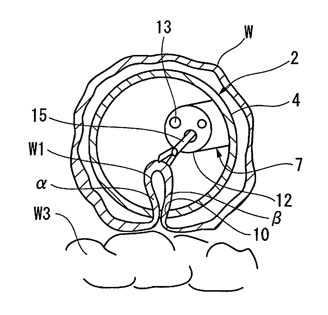
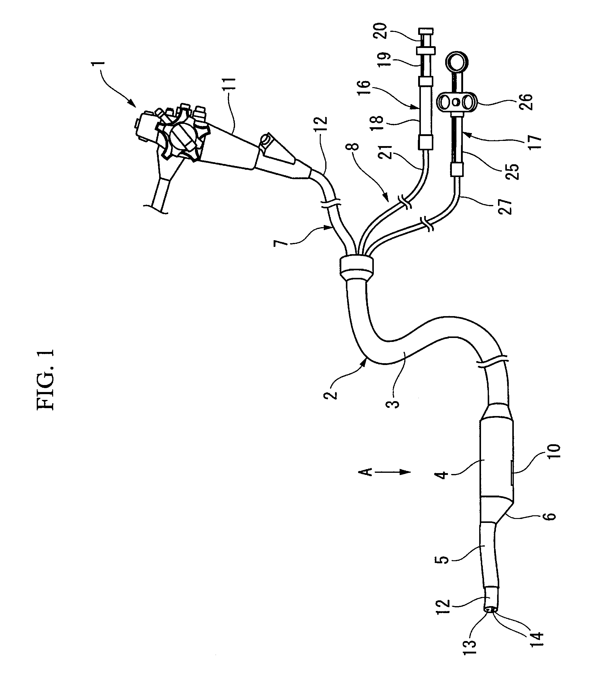
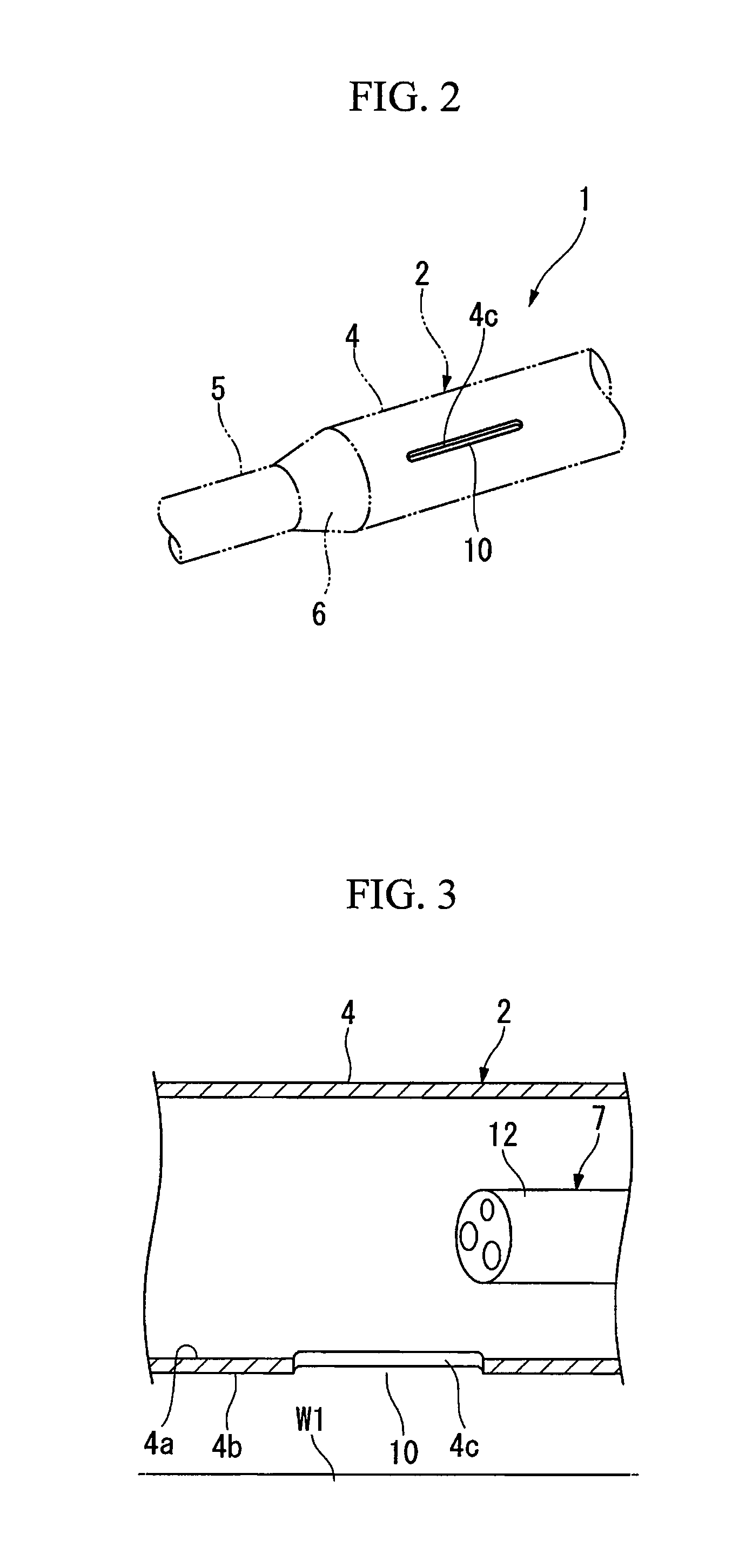
[0164]Hereinafter, a first embodiment will be described in detail with reference to FIGS. 1 to 28.
[0165]As shown in FIG. 1, an endoscopic treatment system 1 includes an elongated overtube 2 serving as a pressing member main body that is inserted into the body of a patient. The overtube 2 is provided with a chamber 4 at a distal end of a flexible tube main body 3. The chamber 4 extends in a cylindrical shape while the diameter thereof is enlarged from the distal end portion of the tube main body 3. A flexible insertion guide 5 is provided on the distal end surface of the chamber 4. The insertion guide 5 is a cylindrical member that is located at a position axially offset with respect to the chamber 4. A transitional portion where the distal end portion of the chamber 4 transitions into the insertion guide 5 is formed as a tapered portion 6 that is cut obliquely toward the insertion guide 5.
[0166]On a more proximal side in the longitudinal direction of the chamber 4 than the tapered p...
embodiment 2
[0211]A second embodiment will be described with reference to FIGS. 34 to 39. Components similar or identical to those of the first embodiment will be referenced by the same reference numerals, and overlapping descriptions will be omitted.
[0212]In the present embodiment, the shape of the lateral hole provided on the chamber is different from that of the first embodiment. That is, as shown in FIG. 34, a lateral hole 100 is an entanglement preventing portion that includes an elongated, first opening 101 and a second opening 102 that is provided to be connected to the distal end side of the first opening 101. The first opening 101 has the same length and width as that of the lateral hole 10 according to the first embodiment. The second opening 102 is formed in a substantially circular shape and has a width greater than that of the first opening 101.
[0213]As shown in FIG. 35, during the procedure, the overtube 2 is inserted with the second opening 102 opposed to the lesion W1, the grasp...
embodiment 3
[0218]A third embodiment will be described with reference to FIGS. 40 to 47. Components similar or identical to those of the afore-described embodiments will be referenced by the same reference numerals, and overlapping descriptions will be omitted.
[0219]As shown in the sectional view of FIG. 40, a lateral hole 110 is formed in the chamber 4. The width of the lateral hole 110 in the circumferential direction of the chamber 4 is sufficiently larger than the thickness of the total layers of the lesion W1 to be drawn in. Here, on the inner circumference of the chamber 4, a slider cover 111 serving as the entanglement preventing portion is attached so as to be freely movable in the circumferential direction. The slider cover 111 includes a first surface 111A which is the inner circumferential surface opposed to the endoscope 7, and a second surface 111B which is the outer circumferential surface opposed to the treatment target portion. The slider cover 111 has a size that can cover the ...
PUM
 Abstract
Description
Claims
Application Information
 - R&D
- Intellectual Property
- Life Sciences
- Materials
- Tech Scout
- Unparalleled Data Quality
- Higher Quality Content
- 60% Fewer Hallucinations
Browse by: Latest US Patents, China's latest patents, Technical Efficacy Thesaurus, Application Domain, Technology Topic, Popular Technical Reports.
© 2025 PatSnap. All rights reserved.Legal|Privacy policy|Modern Slavery Act Transparency Statement|Sitemap|About US| Contact US: help@patsnap.com


