Device for determining a condition of flow in a respiration system

a technology of flow measurement and respiration system, which is applied in the field of devices for determining the flow condition of a respiration system, can solve the problems of difficult construction of compact respiration system, and achieve the effect of reducing the space requirement for flow measurement and non-return valves, improving functions, and reducing the number of elements

Inactive Publication Date: 2009-12-17
DRAGERWERK AG
View PDF8 Cites 13 Cited by
  • Summary
  • Abstract
  • Description
  • Claims
  • Application Information

AI Technical Summary

Benefits of technology

[0005]The object of the present invention is to improve the functions of flow measurement and of the nonreturn valve in a compact embodiment. The essential advantage that the space requirement for the flow measurement and nonreturn valve can be reduced is obtained by the combination of the nonreturn valve and the flow sensor. Another advantage arises from the reduction of the number of elements in the respiration system, which reduces the susceptibility to error and improves maintenance friendliness.

Problems solved by technology

One drawback of this process is, however, the fact that these hot wire sensors require a defined flow situation, which requires a certain section for homogenizing the flow and hence a certain overall length.
This makes it difficult to construct a compact respiration system.

Method used


Image

  • Device for determining a condition of flow in a respiration system
  • Device for determining a condition of flow in a respiration system
  • Device for determining a condition of flow in a respiration system

Examples


third embodiment

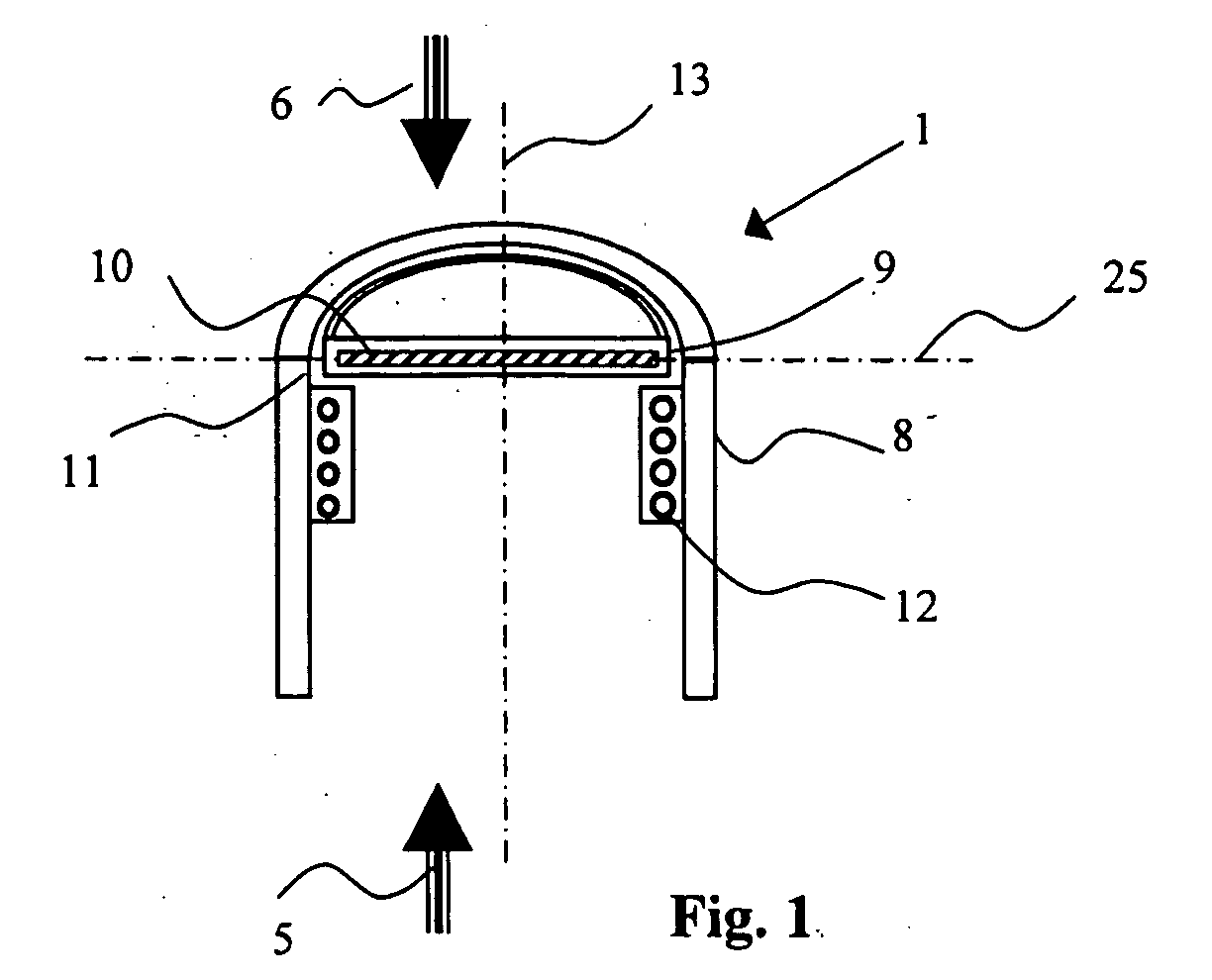
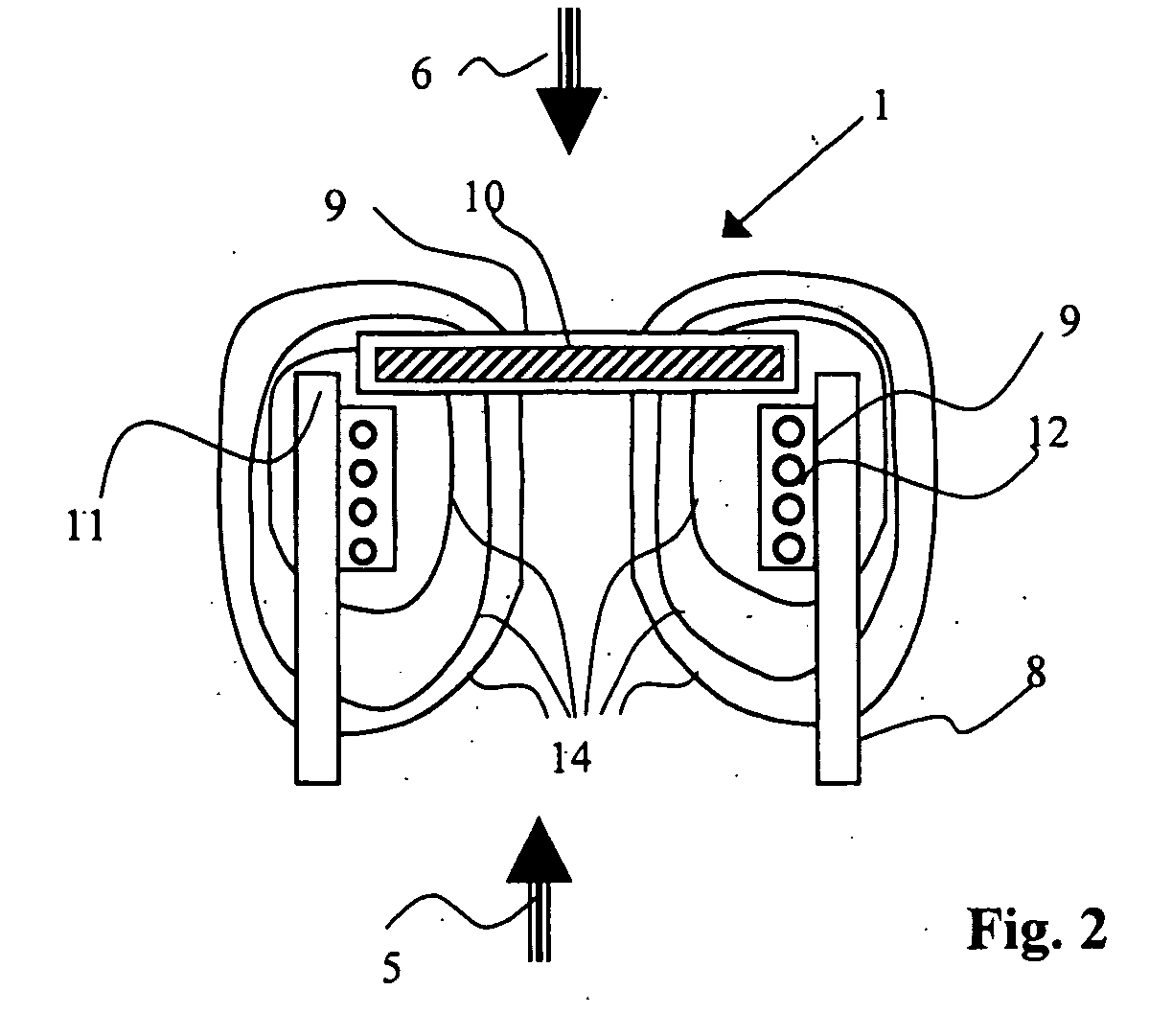
[0061]A coil 12 and a valve element 10 with a contact arrangement, comprising electrical contact elements 26 and an electrical contact bridge 27, are arranged at the valve body 8 in this variant. Analysis of the contact connection can be used in this variant to recognize the phase of breathing, for example, to trigger a respirator. The position of valve element 10 in or at the third embodiment valve disk 28 in relation to the coil arranged around the coil form does affect the properties of the magnetic field.

[0062]The change in the magnetic field properties is analyzed by means of an operating electronic unit (FIG. 4) and it yields a quantitative indicator of flow as an additional measured variable besides the recognition of the phase of breathing.

first embodiment

[0063]In a variant of the first embodiment according to the present invention, the valve disk is held in an inoperative position by a prestressed mechanical spring element 60 as shown in FIG. 14. The characteristic of the spring 60 is selected to be such that the valve disk is raised by the flow against the spring force. The valve can be used in any desired installation position in such an arrangement, because the spring characteristic essentially determines the path and the position of the valve disk as a function of the flow.

[0064]FIGS. 15a, 15b and 15c shows features in which the detector comprises a photoelectric cell with LED 70 and receiver 72 for the optical detection of the position of a valve disk 90 in relation to the valve seat 110. With the valve closed (FIG. 15a), the optical path of the photoelectric cell is uninterrupted by the valve disk 90. With valve open (FIG. 15b), the optical path of the photoelectric cell is interrupted by the valve disk and the signal of the l...


PUM


Abstract

A device for detecting the condition of flow in a respiration system combines the function of a nonreturn valve with the function of flow measurement in a common device. The device includes a valve arrangement (1) with a valve disk (9) and with a valve body (8), wherein the position of a valve disk (9) in relation to a valve seat (11) is detected. An indicator for a flow and a direction of flow (5), (6) is determined from the position of the valve disk (9). The position of the valve disk (9) can be determined inductively, electrically, electromechanically or optically. The flow and direction of flow (5), (6) determined can be used to control the respiration in a medical device.

Description

CROSS REFERENCE TO RELATED APPLICATIONS[0001]This application claims the benefit of priority under 35 U.S.C. § 119 of German Patent Application DE 10 2008 028 733.4 filed Jun. 17, 2008, the entire contents of which are incorporated herein by reference.FIELD OF THE INVENTION[0002]The present invention pertains to a device for recognizing oncoming flow effects at passively acting nonreturn valves. Determination of the volume flow, which is introduced into the patient, and of the quantity of breathing gas, which the patient again breathes out, is of considerable significance in the area of medical anesthesiology apparatus. For example, the absolute quantity of an anesthetic administered to a patient during anesthesia can be deduced from this. The absolute quantity of an anesthetic introduced is in turn a critical parameter in anesthesia, which should be known as exactly as possible. It is therefore important precisely in medical engineering to determine this variable as exactly as poss...

Claims


Application Information

Patent Timeline
Patent Type & Authority Applications(United States)
IPC IPC(8): A61B5/087A61M16/20
CPCA61B5/0876A61M16/0051A61M2205/3317A61M2016/0021A61M2016/0039A61M16/208A61M16/209A61M16/0063A61M16/022
Inventor KULLIK, GOTZHANSMANN, HANS-ULLRICHSETTGAST, DIETER
Owner DRAGERWERK AG
Why Eureka
Try Eureka