Techniques for measuring ion beam emittance

Active Publication Date: 2009-12-24
VARIAN SEMICON EQUIP ASSOC INC
View PDF3 Cites 4 Cited by
  • Summary
  • Abstract
  • Description
  • Claims
  • Application Information

AI Technical Summary

Benefits of technology

[0028]In accordance with further aspects of this particular exemplary embodiment, the first mask may include one or more first mask slits parallel to an Y-Z plane and one or more first mask collectors corresponding to each of the one or more first mask slits

Problems solved by technology

However, ribbon beams, as well as spot beams, can suffer from intrinsic non-uniformity problems.
Furthermore, the beamlets may not be evenly spaced within the ribbon beam.
Therefore, a ribbon beam may lack angle uniformity and / or dose uniformity.
Therefore, a considerable number of ions may be lost before they reach the target wafer as when using low-energy ion beams.
However, because forces associated with space charge effects may be highly non-linear (especially if the ion beam 10 is not elliptical), tuning voltages of deceleration lenses may be very challenging without accurate tuning assistance to compensate for space charge effects.
Although these additional electric and / or magnetic components have been utilized in conventional ion implanters to somewhat improve either angle uniformity and / or dose uniformity of an ion beam, a more efficient solution has yet to be made available for providing ion beams that meet current dose and angle uniformity requirements for ion implantation production.
Such stringent uniformity requirements are becoming more difficult to meet since both types of uniformity may be elusive, especially in semiconductor manufacturing which require relatively high specificity and reliability.

Method used


Image

  • Techniques for measuring ion beam emittance
  • Techniques for measuring ion beam emittance
  • Techniques for measuring ion beam emittance

Examples


Embodiment Construction

[0041]Embodiments of the present disclosure improve upon the above-described techniques by providing techniques for measuring ion beam emittance. More specifically, embodiments of the present disclosure provide techniques for measuring ion beam emittance by using a beam emittance measurement assembly in various configurations and / or positions so that beam emittance measurements may be used to control and tune ion beam angle and density uniformity in ion implantation operations.

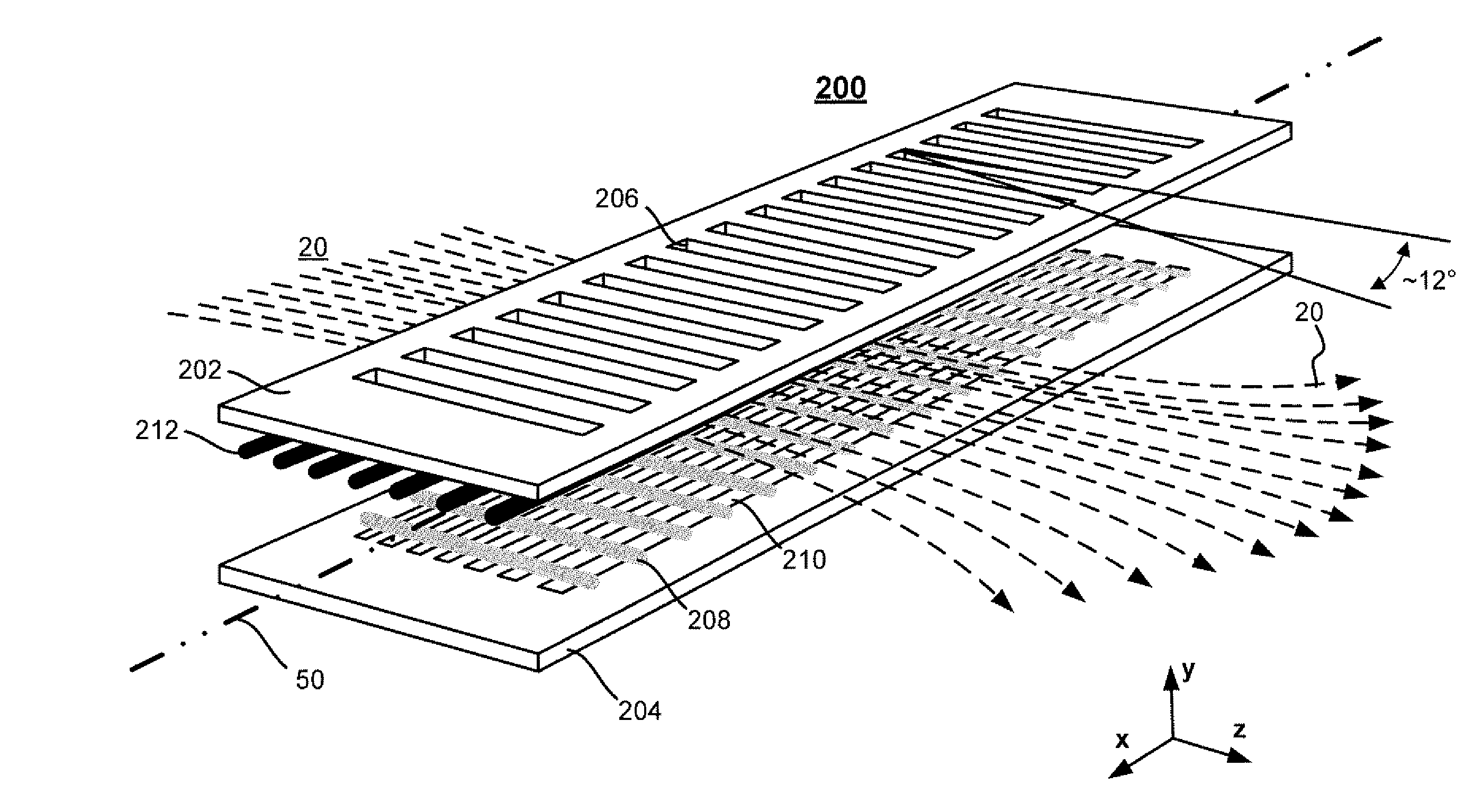
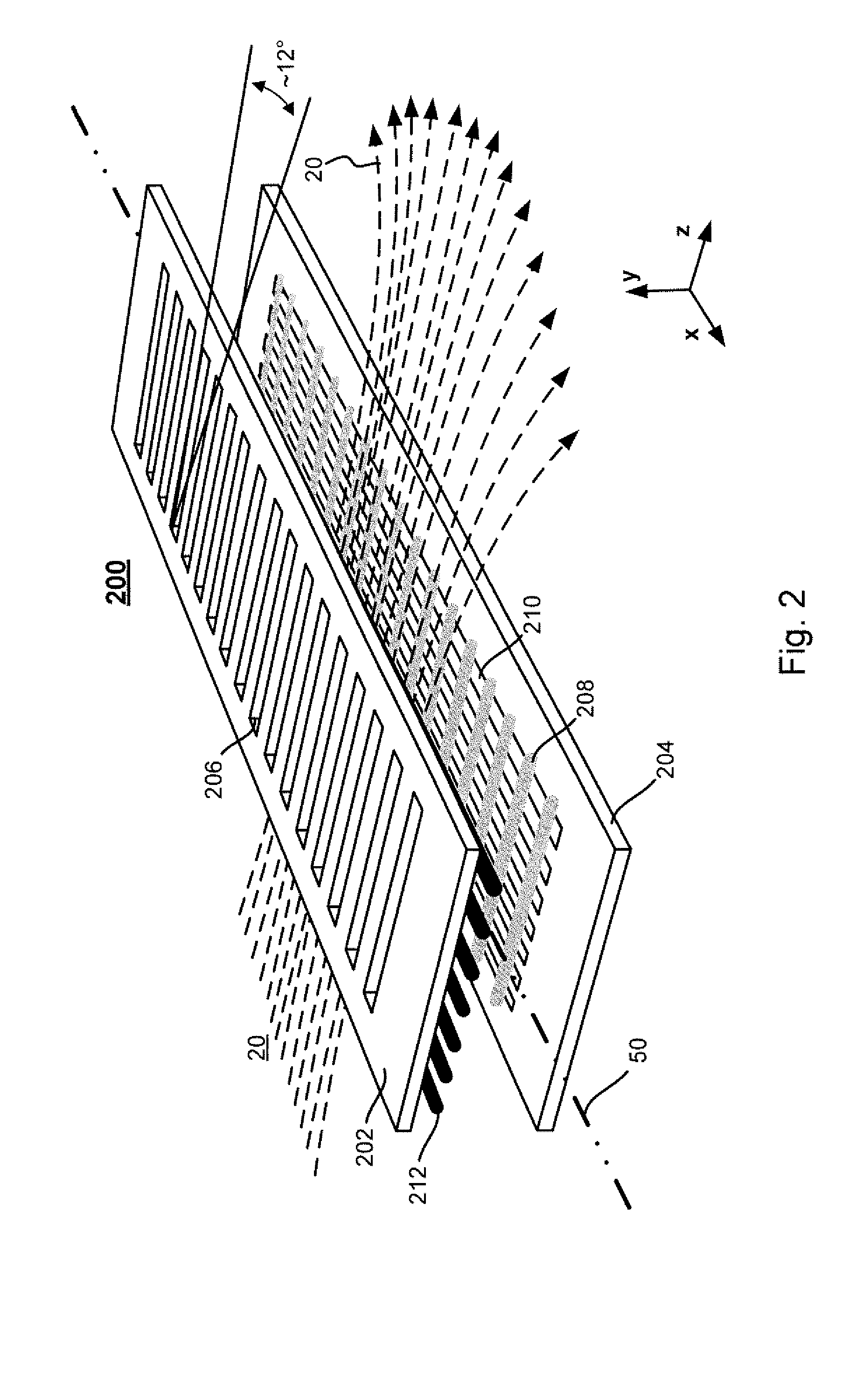
[0042]FIG. 2 depicts a measurement assembly 200 according to an embodiment of the present disclosure. For example, the measurement assembly 200 may be a beam emittance measurement assembly having an “X” mask (“X mask”) 202 and a “Y” mask (“Y mask”) 204. In one embodiment, the X mask 202 and / or the Y mask 204 may be formed of a graphite material. Graphite may be selected as a benign contaminant and for its superior mechanical and thermal properties. In another embodiment, the X mask 202 and / or the Y mask 204 ma...


PUM


Abstract

Techniques for measuring ion beam emittance are disclosed. In one particular exemplary embodiment, the techniques may be realized as an apparatus for measuring ion beam emittance. The apparatus may comprise a measurement assembly comprising a first mask, a second mask, and a pivot axis, such that the measurement assembly rotates about the pivot axis in order to scan an ion beam using either the first mask or the second mask to measure ion beam emittance for providing a measure of ion beam uniformity.

Description

FIELD OF THE DISCLOSURE[0001]The present disclosure relates generally to ion implantation and, more particularly, to techniques for measuring ion beam emittance.BACKGROUND OF THE DISCLOSURE[0002]Ion implanters are widely used in semiconductor manufacturing to selectively alter conductivity of materials. In a typical ion implanter, ions generated from an ion source are directed through a series of beam-line components which include one or more analyzing magnets and a plurality of electrodes. The analyzing magnets select desired ion species, filter out contaminant species and ions having undesirable energies, and adjust ion beam quality at a target wafer. Suitably shaped electrodes may modify the energy and the shape of an ion beam.[0003]In production, semiconductor wafers are typically scanned with an ion beam. As used hereinafter, “scanning” of an ion beam refers to the relative movement of an ion beam with respect to a wafer or substrate surface.[0004]An ion beam is typically eithe...

Claims


Application Information

Patent Timeline
IPC IPC(8): G12B13/00
CPCH01J37/3171
Inventor BENVENISTE, VICTOR M.
Owner VARIAN SEMICON EQUIP ASSOC INC
Why Eureka
Try Eureka