Duplexer

a technology of duplexers and splicers, applied in the field of duplexers, can solve problems such as significant amount of intermodulation distortion (imd)

Active Publication Date: 2009-12-24
MURATA MFG CO LTD
View PDF11 Cites 17 Cited by
  • Summary
  • Abstract
  • Description
  • Claims
  • Application Information

AI Technical Summary

Benefits of technology

[0006]To overcome the problem described above, preferred embodiments of th

Problems solved by technology

Since a BAW piezoelectric resonator, which is inferior to a SAW resonator in secondary non-linear characteristics, is

Method used


Image

  • Duplexer
  • Duplexer
  • Duplexer

Examples


first preferred embodiment

[0029]A duplexer 100 according to a first preferred embodiment of the present invention is described below with reference to FIGS. 1 to 5F.

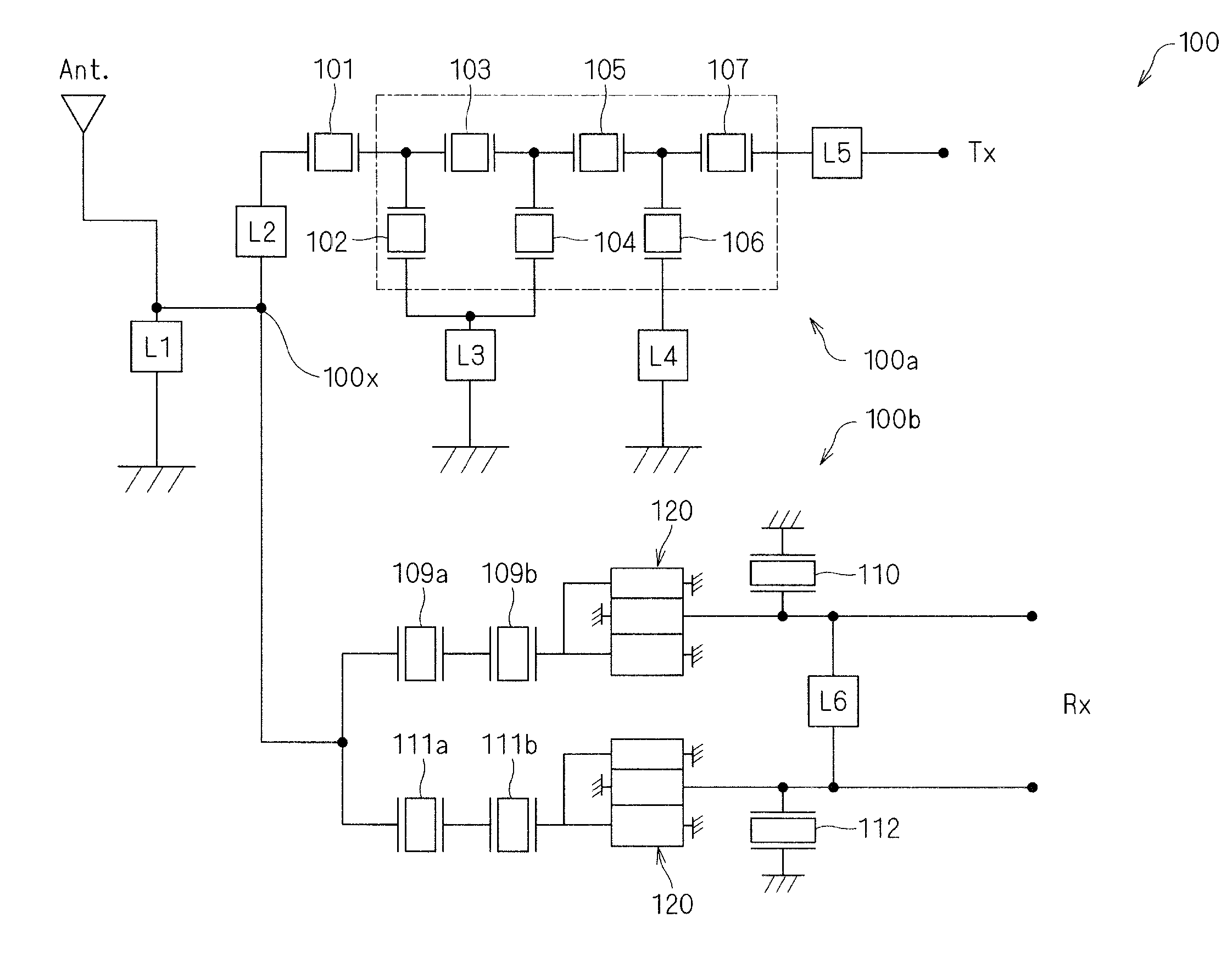
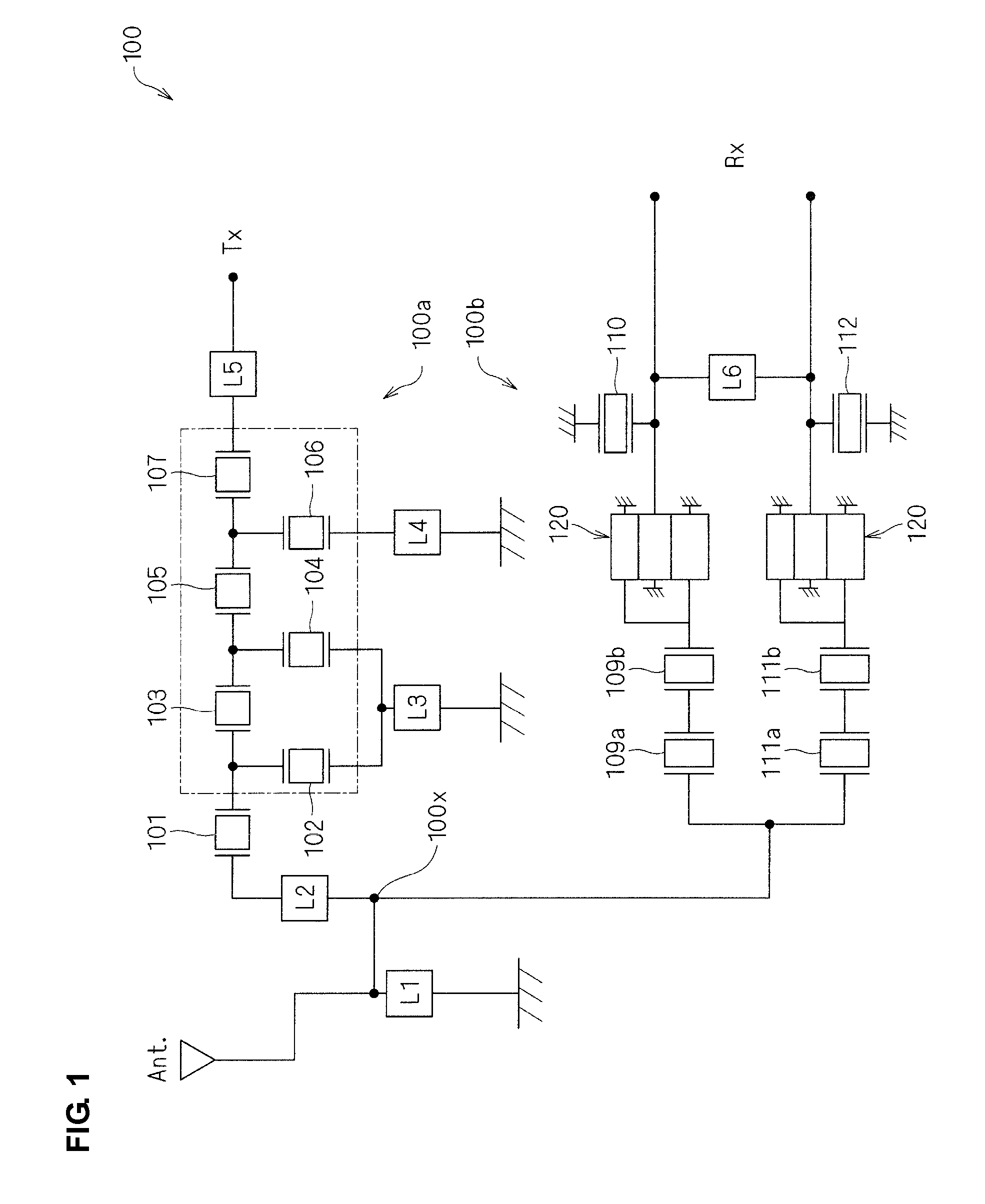
[0030]Referring to FIG. 1, the duplexer 100 preferably includes a transmitting filter 100a arranged between an antenna terminal and a Tx terminal and a receiving filter 100b arranged between the antenna terminal and an Rx terminal. The duplexer 100 includes resonators 101-112 and longitudinally coupled filters 120. Preferably, inductors L1-L7 may be included in the duplexer 100 or may be external to the duplexer 100, for example.

[0031]Preferably, the transmitting filter 100a arranged between the antenna terminal and the Tx terminal includes four serial resonators 101, 103, 105, and 107 and three parallel resonators 102, 104, and 106 that are connected in a ladder configuration. The receiving filter 100b arranged between the antenna terminal and the Rx terminal includes resonators 109a, 109b, 110, 111a, 111b, and 112 and the longitudinally coupled...

second preferred embodiment

[0066]A duplexer 200 according to a second preferred embodiment of the present invention is described below with reference to FIG. 6.

[0067]The duplexer 200 of the second preferred embodiment of the present invention is generally identical in structure to the duplexer of the first preferred embodiment. The difference between the two duplexers is described below.

[0068]As shown in the circuit diagram of FIG. 6, the duplexer 200 includes a transmitting filter 200a arranged between an antenna terminal and a Tx terminal and a receiving filter 200b arranged between the antenna terminal and an Rx terminal. More specifically, the duplexer 200 includes resonators 201-212 and longitudinally coupled filters 220. Preferably, inductors L1-L7 may be included in the duplexer 200 or may be external to the duplexer 200.

[0069]The transmitting filter 200a in the duplexer 200 according to the second preferred embodiment is different from the transmitting filter 100a in the first preferred embodiment. Mo...


PUM


Abstract

A duplexer includes a transmitting filter including serial resonators and parallel resonators connected in a ladder configuration, and a receiving filter. A resonator of the serial resonators and the parallel resonators in the transmitting filter that is arranged closest to a common terminal of the transmitting filter and the transmitting filter includes a surface acoustic wave resonator, and at least one resonator excluding the resonator that is arranged closest to the common terminal includes a film bulk acoustic wave resonator.

Description

BACKGROUND OF THE INVENTION[0001]1. Field of the Invention[0002]The present invention relates to duplexers and, in particular, to a duplexer for use in a mobile telephone system, for example.[0003]2. Description of the Related Art[0004]A duplexer for separating transmission and reception signals in a mobile radio wave band is disclosed in Japanese Unexamined Patent Application Publication No. 2008-504756. As illustrated in a circuit diagram of FIG. 7, the disclosed duplexer includes a receiving filter 1, arranged in a reception path RX, which operates using a surface acoustic wave (SAW) and a transmitting filter 2, arranged in a transmission path TX, which operates using a bulk acoustic wave (BAW).[0005]Since a BAW piezoelectric resonator, which is inferior to a SAW resonator in secondary non-linear characteristics, is used in the transmitting filter of the duplexer, a significant amount of intermodulation distortion (IMD) is generated.SUMMARY OF THE INVENTION[0006]To overcome the p...

Claims


Application Information

Patent Timeline
IPC IPC(8): H03H9/00
CPCH03H9/0028H03H9/725H03H9/706
Inventor UMEDA, KEIICHIUESAKA, KENICHIMIYAKE, TAKASHI
Owner MURATA MFG CO LTD
Why Eureka
Try Eureka