Transmission optical fiber

Inactive Publication Date: 2005-03-29
ELECTRONICS & TELECOMM RES INST
View PDF5 Cites 0 Cited by
  • Summary
  • Abstract
  • Description
  • Claims
  • Application Information

AI Technical Summary

Benefits of technology

The present invention is contrived to solve the above problems and an object of the present invention is to provide a transmission optical fiber that can increase a Raman

Problems solved by technology

However, this significantly increases the non-linear characteristic of the optical

Method used


Image

  • Transmission optical fiber
  • Transmission optical fiber
  • Transmission optical fiber

Examples


Embodiment Construction

The present invention will be described in detail by way of a preferred embodiment with reference to accompanying drawings.

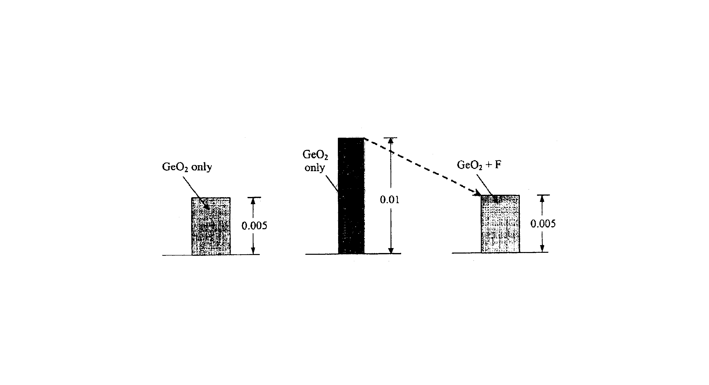
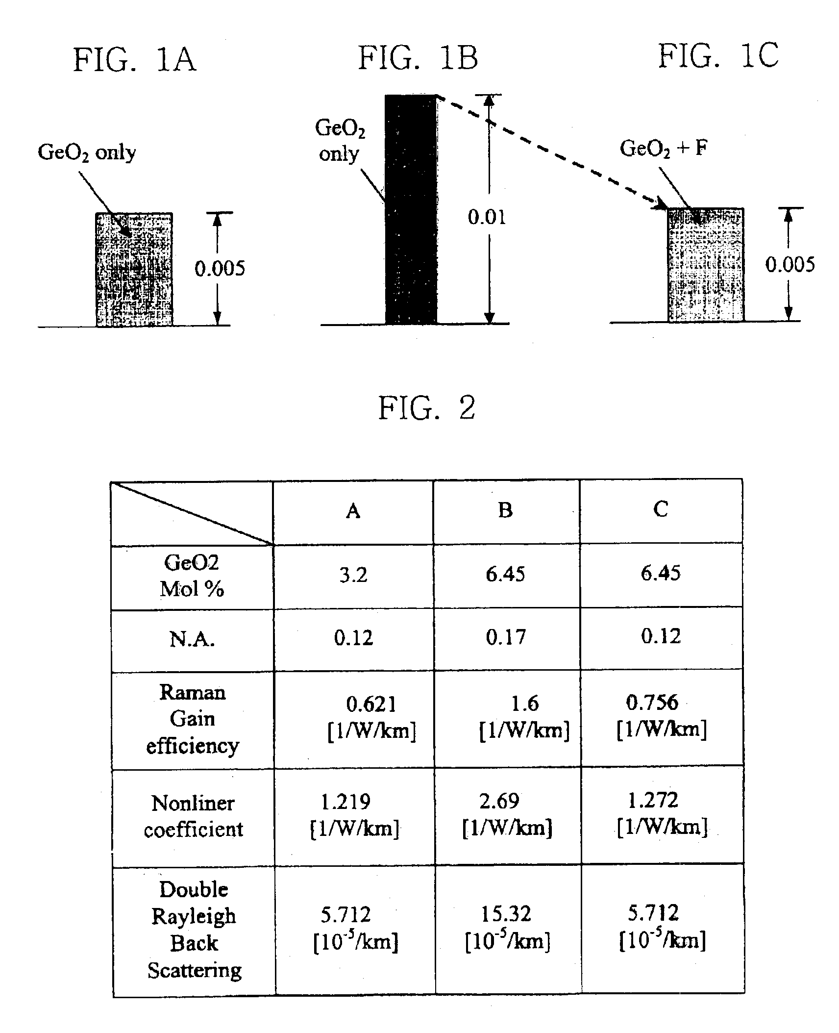
The present invention is characterized in that fluorine (F) is doped to the core or the cladding while GeO2 is added to them, in order to design a transmission optical fiber capable of obtaining a high Raman gain coefficient and reducing double Rayleigh back scattering and non-linearity. Therefore, an increase in the refractive index by GeO2 is reduced and the concentration of GeO2 in the core can be fabricated higher, so that the Raman optical gain is increased. At this time, it is preferred that the range of the concentration of GeO2 in the core is in range of 3.0˜10 mol %, and the concentration of fluorine is in range of 0.1˜5 mol %. It is characterized in that the range of the refractive index of the core is kept higher by the range of 0.003˜0.015 than pure SiO2. The refractive index is increase by controlling GeO2. At this time, the entire refractive index ...


PUM

PropertyMeasurementUnit
Concentrationaaaaaaaaaa
Refractive indexaaaaaaaaaa

Abstract

The present invention relates to a transmission optical fiber. The transmission optical fiber including a core and a cladding made of SiO2 is characterized in that GeO2 and F are doped in SiO2 of the core and the cladding. Therefore, a high Raman gain coefficient could be obtained while a desired dispersion value and a non-linearity are maintained, by controlling the refractive index of the core and the cladding. Further, the pump power of the laser diode could be reduced and the cost of the laser diode could be lowered accordingly. In addition, the life of the laser diode is extended since the laser diode needs not to be operated at a high output.

Description

BACKGROUND OF THE INVENTION1. Field of the InventionThe invention relates generally to a transmission optical fiber used in optical communication systems, and more particularly to, a transmission optical fiber capable of maintaining an existing dispersion characteristic and also increasing the Raman optical gain with a wide effective cross section.2. Description of the Prior ArtOptical communication is a communication method by which information is received and transmitted using light. In optical communication, an optical fiber transmission line is used as a transmission medium, a semiconductor laser or a light emitting diode is used as the light source, an optical detector is used as a light-receiving unit, and the like. The optical fiber has a dual cylindrical shape in which a core at the central portion is surrounded by a cladding portion. As the refractive index of the core portion is higher than the cladding portion, light is focused on the core portion and proceeds along the o...

Claims


Application Information

Patent Timeline
IPC IPC(8): G02B6/02H01S3/0941H01S3/16H01S3/17H01S3/30
CPCC03C13/046G02B6/02G02B6/02261G02B6/02271H01S3/302H01S3/1691H01S3/1695H01S3/176H01S3/0941
Inventor SEO, HONG-SEOKCHOI, YONG GYUKIM, KYONG HON
Owner ELECTRONICS & TELECOMM RES INST
Why Eureka
Try Eureka