High Q linear controlled variable capacitor using translinear amplifier

a translinear amplifier and capacitor technology, applied in the field of voltage controlled variable capacitors, can solve the problems of significant leakage current problem, non-linear character, and large temperature and process dependence, and achieve the effect of steepness of the steady ramp-up/ramp-down operation and the steep change of total capacitan

Inactive Publication Date: 2009-09-01
DIALOG SEMICONDUCTOR GMBH
View PDF12 Cites 2 Cited by
  • Summary
  • Abstract
  • Description
  • Claims
  • Application Information

AI Technical Summary

Benefits of technology

[0013]In accordance with the objectives of this invention, a circuit to implement a voltage controlled variable capacitor, operating in a linear mode and maintaining High Q-Factor is achieved. The invention disclosed in the referenced patent application (U.S. Ser. No. 10 / 764,920) added circuits and methods to linearize the capacitance change and to minimize the effect of parasitic resistance in the capacitor switching elements, which would degrade Q-factor. The herewith disclosed invention further implements a translinear amplifier and adds additional circuits to further reduce the effect of parasitic resistance and of temperature deviation.
[0028]Even further, a specific non-linear characteristic of the tuning voltage to capacitance relation can be achieved by dimensioning the relation between said tuning voltage and said individual threshold levels as desired. In one proposed solution, the individual steps of the reference resistor chain will be dimensioned to a desired nonlinear curve, for example when the steps between the threshold levels, where the next capacitor starts to be switched on, are narrower in one area than in other areas, more capacitors start to be switched in parallel and a steeper change of total capacitance can be achieved.
[0029]A translinear amplifier typically has a gain of 1. However, a gain different from 1 is also achievable, which, if implemented, gives one more degree of freedom in dimensioning and optimizing certain operating parameters. For example, the remaining overlapping of neighboring capacitor switching stages may be even further reduced, as the steepness of the steady ramp-up / ramp-down operation can be controlled with adequate selection of the gain.
[0031]A further method compensates the temperature effect of the switching device. It generates a temperature dependent compensation voltage by using an identical device-type as the switching device and feeds the resulting signal into the output reference point of the translinear amplifier.

Problems solved by technology

However the characteristics are non-linear and are widely temperature and process dependent.
There is also a significant leakage current problem.
In addition the switching of the individual capacitors causes switching noise (“spikes”) on the common circuit rails.
Furthermore, while the switching transistor is kept in flat switching ramp to smooth the switching steps, the transistor's resistance causes a Q-factor problem.

Method used


Image

  • High Q linear controlled variable capacitor using translinear amplifier
  • High Q linear controlled variable capacitor using translinear amplifier
  • High Q linear controlled variable capacitor using translinear amplifier

Examples


Embodiment Construction

[0054]The objectives of this invention are to control the capacitance of a variable capacitor in a strictly linear mode through a tuning voltage. A fundamental requirement is to achieve a high Q-factor at the same time.

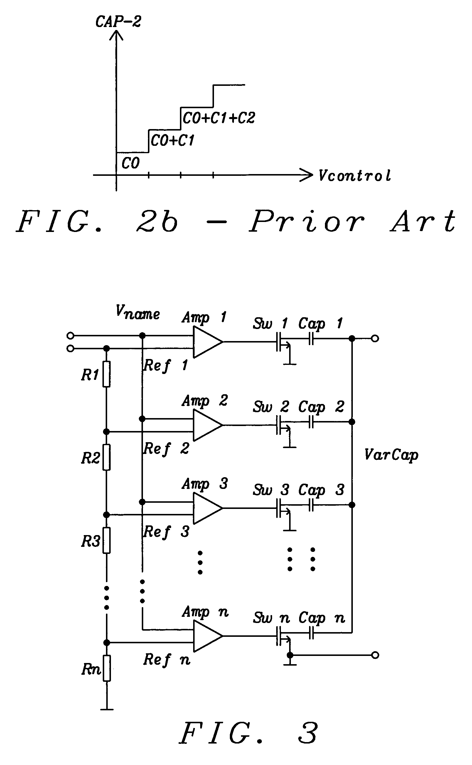
[0055]A discussion of the general principles of a voltage controlled variable capacitor with linear characteristic, formed of a larger number of fixed capacitor segments and a corresponding number of switching elements, using operational amplifiers is disclosed in the related U.S. patent application Ser. No. 10 / 764,920, filed Jan. 26, 2004, the entire contents of which is incorporated herewith by reference.

[0056]FIG. 3 shows a principal circuit diagram of the referenced related patent application. A set of circuits to control the switching operation in a ramp-up / ramp-down manner, contains, typically besides other components, the set of operational amplifiers Amp 1 to Amp n. Sw 1 to Sw n are said switching devices and Cap 1 to Cap n are said capacitors that will be swi...


PUM


Abstract

A voltage controlled variable capacitor, formed of a larger number of fixed capacitor segments and a corresponding number of switching elements, uses translinear amplifiers to control each switching element. Each translinear amplifier linearly switches from the fully off to the fully on state; a minimum number of switching stages (ideally only one) is in the mode-of-change at any one time with a minimum overlap. The arrangement achieves a nearly linear change of capacitance at linear tuning voltage change, while resulting in high Q-factor due to the low RDSon and high RDSoff of the fully switched stages. The invention eliminates temperature and voltage dependencies of other solutions like varactor diodes.

Description

RELATED PATENT APPLICATION[0001]This application is related to U.S. patent application Ser. No. 10 / 764,920 filed concurrently herewith on Jan. 26, 2004 and U.S. patent application Ser. No. 10 / 676,919 filed Oct. 1, 2003, now issued as U.S. Pat. No. 6,937,098, and assigned to the same assignee as the present invention.BACKGROUND OF THE INVENTION[0002](1) Field of the Invention[0003]The invention relates to a voltage controlled variable capacitor, and more particularly, to a variable capacitor, formed of a larger number of fixed capacitor segments and a corresponding number of switching elements, which are typically integrated with the capacitance controlling functions on an integrated semiconductor circuit.[0004](2) Description of Prior Art[0005]One example of a voltage-controlled capacitor is a varactor diode. When a reverse voltage is applied to a PN junction, it creates a depletion region, essentially devoid of carriers, which behaves as the dielectric of a capacitor. The depletion...

Claims


Application Information

Patent Timeline
Patent Type & Authority Patents(United States)
IPC IPC(8): G06F7/64H03H11/12
CPCH03H11/1291
Inventor SIBRAI, ANDREASNIEDERL, JOSEF
Owner DIALOG SEMICONDUCTOR GMBH
Why Eureka
Try Eureka