Home security system using an ad-hoc wireless mesh and method thereof

a home security and wireless mesh technology, applied in multiplex communication, frequency-division multiplex, instruments, etc., can solve the problems of not providing any warning to the homeowner, laying the cable is also an expensive proposition, monitoring systems do not monitor valuable assets, etc., to reduce the power consumed by the communication nodes and the effect of little power

Inactive Publication Date: 2009-12-24
TANLA SOLUTIONS LTD
View PDF8 Cites 100 Cited by
  • Summary
  • Abstract
  • Description
  • Claims
  • Application Information

AI Technical Summary

Benefits of technology

[0018]Moreover, the one or more ad-hoc mesh networks are capable of adapting themselves to failure of one or more communication nodes. The one or more ad-hoc mesh networks are also capable of determining newly added communication nodes and integrating them in the one or more ad-hoc mesh networks. This provides the necessary flexibility to the automation and security system as communication nodes may be added or removed without any need for substantial modification to the one or more ad-hoc mesh networks.
[0019]In one aspect of the present invention, the communication nodes configuring the one or more ad-hoc mesh networks are coupled with each other using low power / low range radio frequency (RF) transceivers. To provide real-time notification to the end user of the system, the communication nodes need to be operative all the time. The low power / low range RF transceivers consume very little power and thereby help in reducing the power consumed by the communication nodes.

Problems solved by technology

However, such monitoring systems do not provide any warning to the homeowner of a possible intruder presence.
Moreover, the monitoring systems do not monitor the valuable assets which are placed near the monitored area.
Laying the cable is also an expensive proposition, and the length of the cable moreover serves to limit the way the security devices are connected to the central monitoring station.
Further, in such a set-up, any addition / removal of such devices is a cumbersome process and might require the need to upgrade the central monitoring station to handle a new configuration.
But the existing wireless systems are set-up in point-to-point communication with the central monitoring station, thereby limiting the way in which these devices are deployed in the network.
Moreover, typically these devices are deployed in a fixed network which makes it very difficult to integrate them with other networks.
Further, any addition / removal of these devices requires re-programming of the central monitoring station.
In order to convey the monitored data in real-time, these devices need to be activated 99% of the time, which results in substantial power consumption.
The monitored data is detected only when the devices are in wake-up mode, resulting in a delay in the transmission to the central monitoring station.
These monitoring systems may also suffer from a failure of the network.

Method used


Image

  • Home security system using an ad-hoc wireless mesh and method thereof
  • Home security system using an ad-hoc wireless mesh and method thereof
  • Home security system using an ad-hoc wireless mesh and method thereof

Examples


Embodiment Construction

[0029]The exemplary embodiments described herein detail for illustrative purposes and are subject to many variations in structure and design. It should be emphasized, however, that the present invention is not limited to a particular automation and security system, as shown and described. It is understood that various omissions and substitutions of equivalents are contemplated as circumstances may suggest or render expedient, but these are intended to cover the application or implementation without departing from the spirit or scope of the claims of the present invention. Also, it is to be understood that the phraseology and terminology used herein is for the purpose of description and should not be regarded as limiting. The terms “a” and “an” herein do not denote a limitation of quantity, but rather denote the presence of at least one of the referenced item.

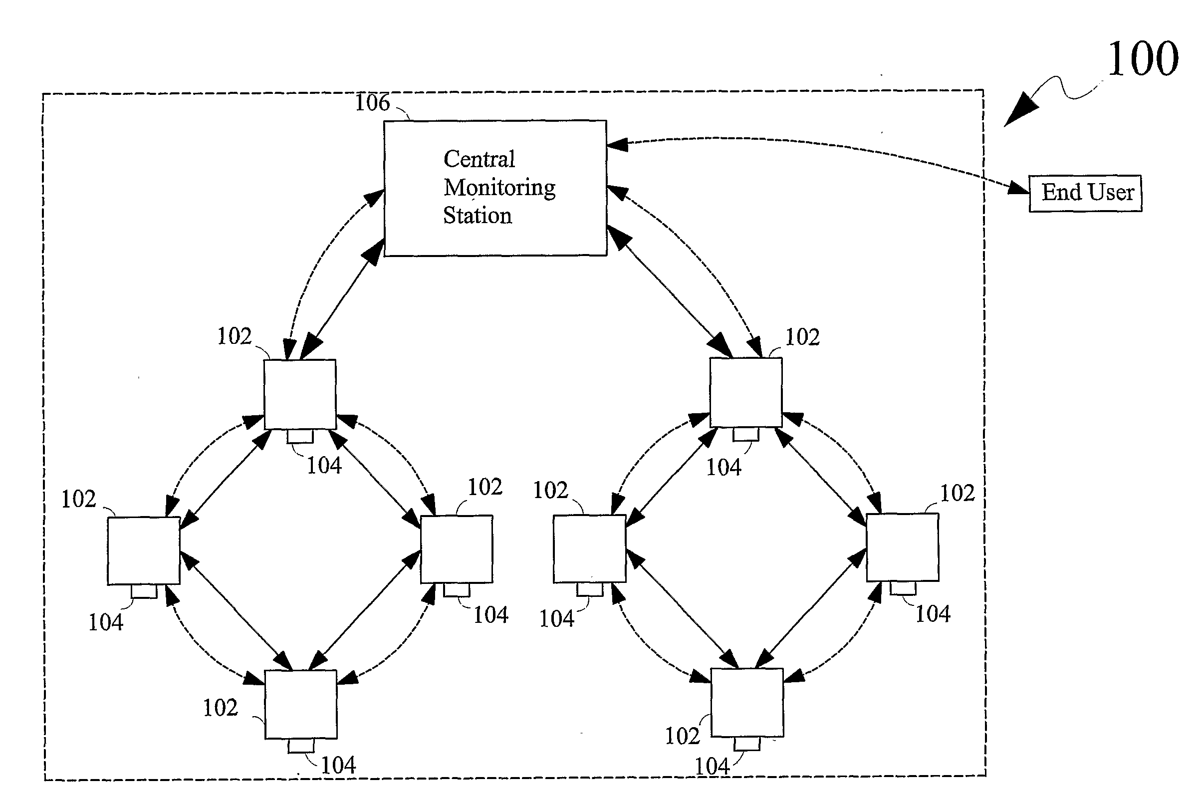
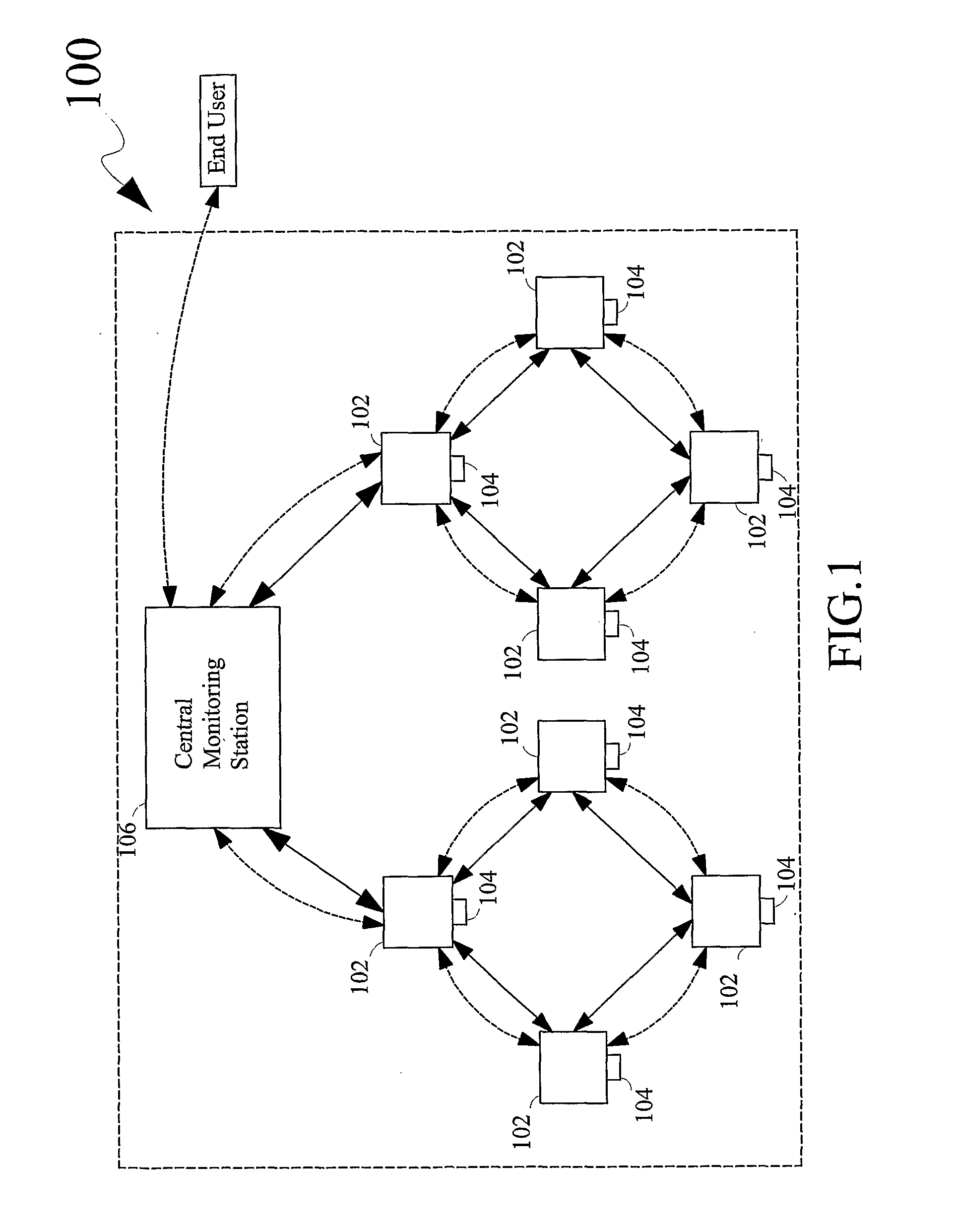
[0030]The present invention provides a system and a method for providing automatic real-time notification to an end user of an...


PUM


Abstract

An automation and security system includes a plurality of communication nodes configuring one or more ad-hoc mesh networks. The communication nodes are operatively coupled with at least one of an automation device and/or a security device. The automation and/or the security device senses the occurrence of a situation and communicates a situation data of the situation in real-time to the communication nodes. The situation data is then dynamically routed over the ad-hoc mesh network to a central monitoring station which then automatically processes the situation data to provide a real-time notification to the end user of the system.

Description

FIELD OF THE INVENTION[0001]The present invention relates to automated solutions for remote notification, and, more specifically, relates to an automation and security system which provides real-time notification of a situation to an end user, using one or more ad-hoc mesh networksBACKGROUND OF THE INVENTION[0002]Remote monitoring systems provide an end user of the monitoring system with access to desired data from remote locations. In addition to being cost-effective and convenient, such monitoring systems provide an efficient and reliable solution for delivering data to the end user of the monitoring system. For instance, the usage of utility commodities, such as electricity, water, gas, steam and the like, is conveniently determined by utility service providers using automation devices such as light meter readers, gas meter readers and the like. The monitoring systems in this case employ technologies and methods for remotely reading a plurality of utility meters that allow usage ...

Claims


Application Information

Patent Timeline
Patent Type & Authority Applications(United States)
IPC IPC(8): G08B1/08H04W40/00H04W84/18
CPCG08B25/009G08G1/205H04L45/3065H04W84/18H04W4/12H04W40/00H04L47/125G08B25/004G08B29/16
Inventor SATISH, KATHIRISETTINAVNIT, CHACHANREDDY, DASARI UDAY KUMAR
Owner TANLA SOLUTIONS LTD
Why Eureka
Try Eureka