Image forming method and apparatus

Inactive Publication Date: 2009-12-24
FUJIFILM CORP
View PDF4 Cites 55 Cited by
  • Summary
  • Abstract
  • Description
  • Claims
  • Application Information

AI Technical Summary

Benefits of technology

[0042]According to this aspect of the present invention, since the amount of water originating from the aqueous ink and still remaining on each of the portions after the drying is controlled so as to be 4.0 g/m2 or less, then it is possible to prevent offset and it is also possible to prevent curl caused by an excessive amount of water remaining on the recording medium, more effectively.
[0043]Preferably, when an amount of water in the aqueous ink deposited on each of the portions before the drying is not less than 6.0 g/m2, then the drying control device controls the ink drying unit so as to control the degree of drying of each of the portions in such a manner that the amount of water originating from the aqueous ink and still remaining on each of the portions aft

Problems solved by technology

In the inkjet recording system, when ink droplets are consecutively deposited in such a manner that the ink droplets (ink dots) that are mutually adjacent on the recording medium overlap with each other, these ink droplets combine together due to their surface tension and give rise to a problem of bleeding (landing interference) in which the desired dots cannot be formed.
In the case of dots of the same color, the dots shape is disturbed and in the case of dots of different colors, an additional problem of color mixing occurs.
In particular, when recording with a single-pass system using a line head, the difference in the landing time between mutually adjacent ink droplets is short and therefore landing interfere

Method used


Image

  • Image forming method and apparatus
  • Image forming method and apparatus
  • Image forming method and apparatus

Examples


examples

[0260]There follows a description of examples of the present invention.

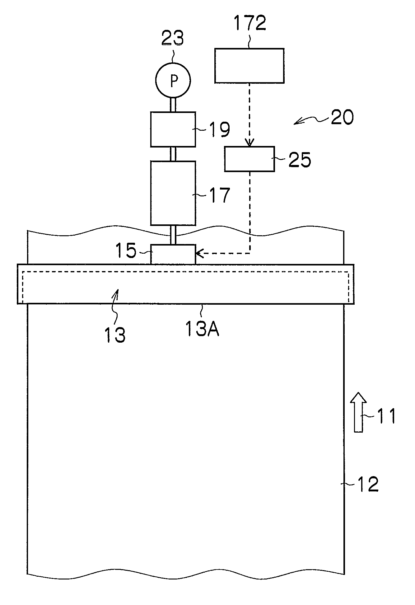
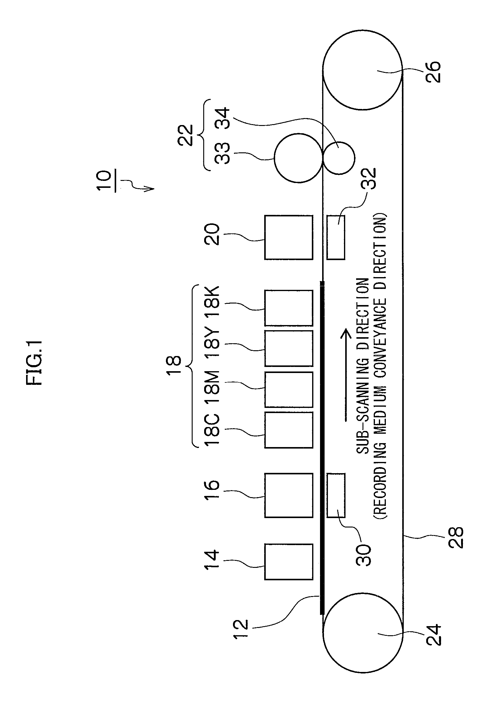
[0261]The compositions of the treatment liquid (aggregating treatment liquid) and the ink, the types of the recording media, experimental conditions, and criteria of the results of the experiments of the example of the present invention were as described below. As the image forming apparatus, the apparatus having the composition shown in FIG. 1 was used.

Preparation of the Treatment Liquid

[0262]A treatment liquid was prepared by mixing together the following materials:

Citric acid (made by Wako Pure Chemical Industries):16.7 wt %Diethylene glycol monomethyl ether (made by Wako Pure20.0 wt %Chemical Industries):Zonyl FSN-100 (made by Dupont): 1.0 wt %Deionized water:62.3 wt %

[0263]The physical properties of the treatment liquid thus prepared were measured as: the viscosity was 4.9 mPa·s, the surface tension was 24.3 mN / m and the pH was 1.5.

Preparation of the Ink

1>

[0264]88 g of methylethyl ketone was introduced into ...


PUM

PropertyMeasurementUnit
Thicknessaaaaaaaaaa
Pressureaaaaaaaaaa
Volumeaaaaaaaaaa

Abstract

The image forming method forms an image on a recording medium by using aqueous ink and treatment liquid. The ink contains coloring material, and the treatment liquid contains a component which reacts with the coloring material. The image forming method includes: a treatment liquid deposition step of depositing the treatment liquid onto the recording medium; an ink deposition step of ejecting and depositing droplets of the aqueous ink in accordance with image information, onto the recording medium on which the treatment liquid has been deposited in the treatment liquid deposition step; an ink drying step of drying an ink layer which has been formed on the recording medium by reaction between the treatment liquid deposited in the treatment liquid deposition step and the aqueous ink deposited in the ink deposition step, such that an amount of water originating from the aqueous ink and still remaining on the recording medium after the ink drying step is not more than 4.0 g/m2; and a fixing step of fixing the ink layer which has been dried in the ink drying step on the recording medium by applying heat and pressure to the ink layer.

Description

BACKGROUND OF THE INVENTION[0001]1. Field of the Invention[0002]The present invention relates to an image forming method and apparatus, and more particularly, to technology in a two-liquid reaction system which forms an image on a recording medium by using an ink and a treatment liquid, for achieving high image quality by preventing the occurrence of offset in a fixing step for fixing the image, and the occurrence of curling of the recording medium, and the like.[0003]2. Description of the Related Art[0004]An inkjet recording system performs recording by ejecting and depositing droplets of ink onto a recording medium from a plurality of nozzles formed in an inkjet head, and such a system is able to record images of high resolution and high quality, with little noise during the recording operation and low running costs. The ink ejection system may be, for example, a piezoelectric system, which uses the displacement of a piezoelectric element, a thermal system, which uses thermal ener...

Claims


Application Information

Patent Timeline
IPC IPC(8): B41J29/38B41J2/01
CPCB41J2/0057B41J11/002B41J11/0015B41J2/2114B41M5/0011B41M5/0017B41M7/009B41M7/00B41J11/0022
Inventor YAMANOBE, JUN
Owner FUJIFILM CORP
Why Eureka
Try Eureka