
Power Supply Device, Input-Output Limit Setting Method in Power Supply Device, Vehicle, and Vehicle Control Method

a technology of power supply device and input-output limit, which is applied in the direction of electric devices, gas pressure propulsion mountings, driver input parameters, etc., can solve the problems of undesirable discomfort of drivers, sudden decrease of motor output power, etc., and achieve the effect of reducing charge current and effectively preventing a significant temperature increase of accumulators

Inactive Publication Date: 2009-12-31
TOYOTA JIDOSHA KK
View PDF5 Cites 29 Cited by
  • Summary
  • Abstract
  • Description
  • Claims
  • Application Information

AI Technical Summary

Benefits of technology

[0003]A conventional technique of preventing a significant temperature increase of the battery in the power supply device simultaneously decreases the output limit of the battery and an input limit as an electric power chargeable into the battery when the temperature of the battery exceeds a predetermined threshold value, so as to reduce both a charge current and a discharge current of the battery. The simultaneous decrease of the input limit and the output limit of the battery, however, abruptly decreases the electric power output from the battery, while preventing a significant temperature increase of the battery. In the power supply device of this structure mounted on a vehicle to be used as an electric power source of a motor for outputting a driving power to an axle, such an abrupt decrease of the output electric power from the battery leads to an abrupt decrease of the output power of the motor and undesirably makes the driver feel odd and uncomfortable. Optimum control of the electric power output from the battery is demanded by adequately setting the input limit and the output limit of the battery.

Problems solved by technology

In the power supply device of this structure mounted on a vehicle to be used as an electric power source of a motor for outputting a driving power to an axle, such an abrupt decrease of the output electric power from the battery leads to an abrupt decrease of the output power of the motor and undesirably makes the driver feel odd and uncomfortable.

Method used


Image

  • Power Supply Device, Input-Output Limit Setting Method in Power Supply Device, Vehicle, and Vehicle Control Method
  • Power Supply Device, Input-Output Limit Setting Method in Power Supply Device, Vehicle, and Vehicle Control Method
  • Power Supply Device, Input-Output Limit Setting Method in Power Supply Device, Vehicle, and Vehicle Control Method

Examples


Embodiment Construction

[0035]One mode of carrying out the invention is described below as a preferred embodiment with reference to the accompanied drawings.

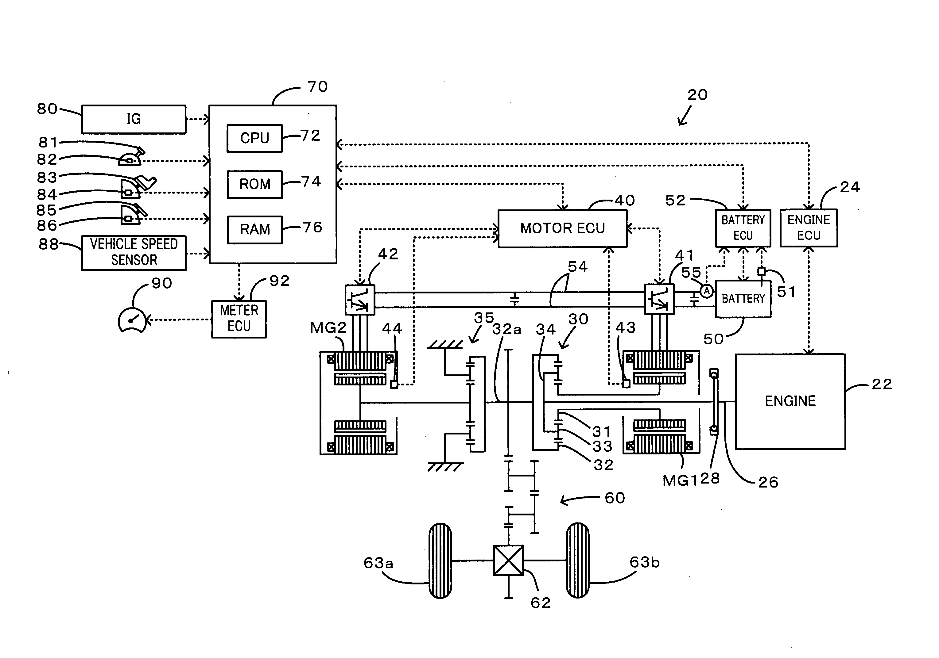
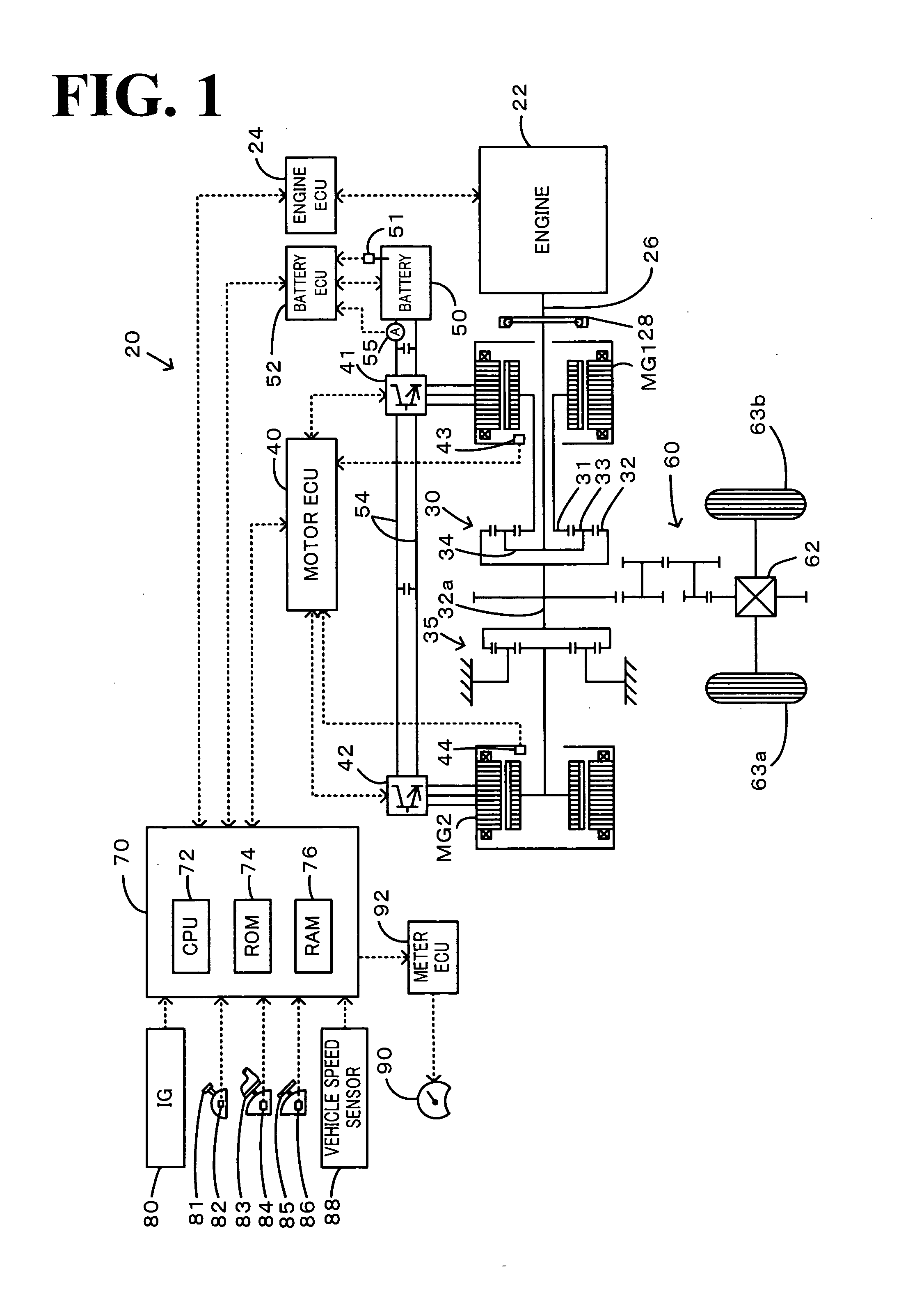
[0036]FIG. 1 schematically illustrates the construction of a hybrid vehicle 20 with a power output apparatus mounted thereon in one embodiment of the invention. As illustrated, the hybrid vehicle 20 of the embodiment includes an engine 22, a three shaft-type power distribution integration mechanism 30 that is linked with a crankshaft 26 functioning as an output shaft of the engine 22 via a damper 28, a motor MG1 that is linked with the power distribution integration mechanism 30 and is capable of generating electric power, a reduction gear 35 that is attached to a ring gear shaft 32a functioning as a drive shaft connected with the power distribution integration mechanism 30, another motor MG2 that is linked with the reduction gear 35, and a hybrid electronic control unit 70 that controls the whole power output apparatus.

[0037]The engine 22 is an intern...


PUM

PropertyMeasurementUnit
electric poweraaaaaaaaaa
temperatureaaaaaaaaaa
chargeaaaaaaaaaa

Abstract

When a time average of square values of charge-discharge current Ib (square mean value Sqib) exceeds a predetermined reference value Sqref and when state of charge SOC of a battery is higher than a preset reference level SOCref1, the procedure of the invention corrects a basic input limit Wintmp set according to a battery temperature Tb and the state of charge SOC and sets the corrected basic input limit Wintmp to an effective input limit Win* (steps S140, S180, and S190). When the state of charge SOC is lower than a preset reference level SOCref2, the procedure of the invention corrects a basic output limit Wouttmp set according to the battery temperature Tb and the state of charge SOC and sets the corrected basic output limit Wouttmp to an effective output limit Wout* (steps S200 and S210). This arrangement of the invention more adequately sets the effective input limit Win* and the effective output limit Wout*, compared with a conventional technique of simultaneously correcting the effective input limit and the effective output limit based on the temperature Tb of the battery.

Description

TECHNICAL FIELD[0001]The present invention relates to a power supply device, an input-output limit setting method in the power supply device, a vehicle, and a vehicle control method.BACKGROUND ART[0002]One proposed structure of a power supply device is equipped with a chargeable and dischargeable battery (see, for example, Patent Document 1). The power supply device of this proposed structure sets an output limit as an electric power dischargeable power from the battery, based on the state of charge and the temperature of the battery, in order to prevent deterioration of the battery due to a decrease in state of charge of the battery or a temperature increase of the battery.Patent Document 1: Japanese Patent Laid-Open No. H10-136502DISCLOSURE OF THE INVENTION[0003]A conventional technique of preventing a significant temperature increase of the battery in the power supply device simultaneously decreases the output limit of the battery and an input limit as an electric power chargeabl...

Claims


Application Information

Patent Timeline
Patent Type & Authority Applications(United States)
IPC IPC(8): B60W10/04G01R31/36G06F19/00B60W20/00B60L3/00H01M10/44H01M10/48H02J7/00H02J7/04
CPCB60K6/365Y02T10/6239B60K6/445B60K6/448B60K6/547B60L11/1861B60L11/187B60L2240/421B60L2240/423B60L2240/486B60W10/06B60W10/08B60W10/26B60W20/00B60W2510/081B60W2510/244B60W2510/246B60W2520/10B60W2540/10B60W2540/12B60W2540/16B60W2710/0644B60W2710/083H02J7/00H02J7/0021H02J7/0078H02J7/009H02J7/0091Y02T10/6234Y02T10/6243Y02T10/6286Y02T10/642Y02T10/7005Y02T10/7044Y02T10/705Y02T10/7055B60K6/442B60L58/12B60L58/24H02J7/00719H02J2310/48H02J7/00714Y02T10/62Y02T10/64Y02T10/70H02J7/0048H02J7/007194B60W20/13H02J7/0047H02J7/007192
Inventor SUZUI, KOSUKE
Owner TOYOTA JIDOSHA KK
Learn More