Nacelle for aircraft comprising means of reversing thrust and aircraft comprising at least one such nacelle

a technology of nacelles and aircraft, which is applied in the direction of machines/engines, climate sustainability, sustainable transportation, etc., can solve the problems of reducing the aerodynamics of the nacelle, not making an effective acoustic treatment possible, and limiting the application of acoustic treatment coatings on the internal surface of the nacell

Active Publication Date: 2009-12-31
AIRBUS OPERATIONS (SAS)
View PDF6 Cites 31 Cited by
  • Summary
  • Abstract
  • Description
  • Claims
  • Application Information

AI Technical Summary

Benefits of technology

[0015]This invention has the advantage of isolating the flaps of the secondary channel in normal operation, i.e. without reversal of the thrust, reducing the misalignments and making it possible to apply a quasi-continuous acoustic treatment on the radially exterior wall of the secondary channel. Furthermore the invention is very robust as it implements only mechanical means and does not require any electrical, hydraulic or pneumatic actuator other than those required to slide the rear mobile portion of the nacelle.
[0018]Each longitudinal bar participates advantageously in the articulation of two flaps, which makes it possible to reduce the number of components.

Problems solved by technology

The interior and exterior flaps connect together with the front and rear portions of the nacelle, but these connections reduce the aerodynamism of the nacelle.
Moreover, they do not make an effective acoustic treatment possible.
As mentioned hereinabove, these configurations limit the application of a coating for acoustic treatment of the internal surface of the nacelle due to the presence of the flaps.
Indeed, the connection zones between the fixed portion and the mobile portion and the zones on which are provided the articulations of the pivoting elements (doors or flaps) cannot include a coating for acoustic treatment.
These configurations also generate aerodynamic losses on flux flowing in the secondary duct due to the numerous spacings and misalignments due to the presence of flaps, and also due to the presence of rods in the secondary channel.
Furthermore, an overload is applied to the internal acoustic panel forming the radially internal wall of the secondary channel during the actuating of the thrust reverser, due to the traction applied by the rods on the internal acoustic panel to open the flaps.

Method used


Image

  • Nacelle for aircraft comprising means of reversing thrust and aircraft comprising at least one such nacelle
  • Nacelle for aircraft comprising means of reversing thrust and aircraft comprising at least one such nacelle
  • Nacelle for aircraft comprising means of reversing thrust and aircraft comprising at least one such nacelle

Examples


first embodiment

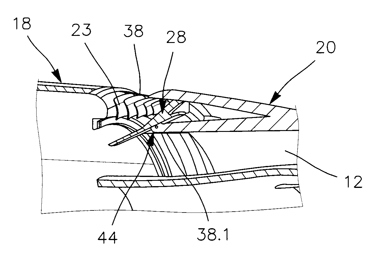
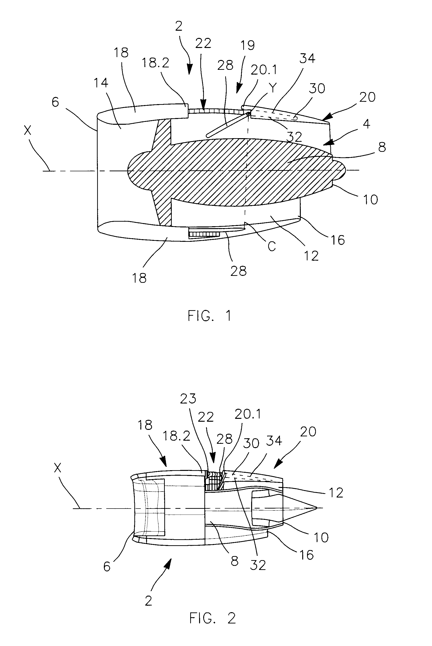
[0028]FIG. 2 is a longitudinal section view of a nacelle according to this invention, with the thrust reverser deployed,

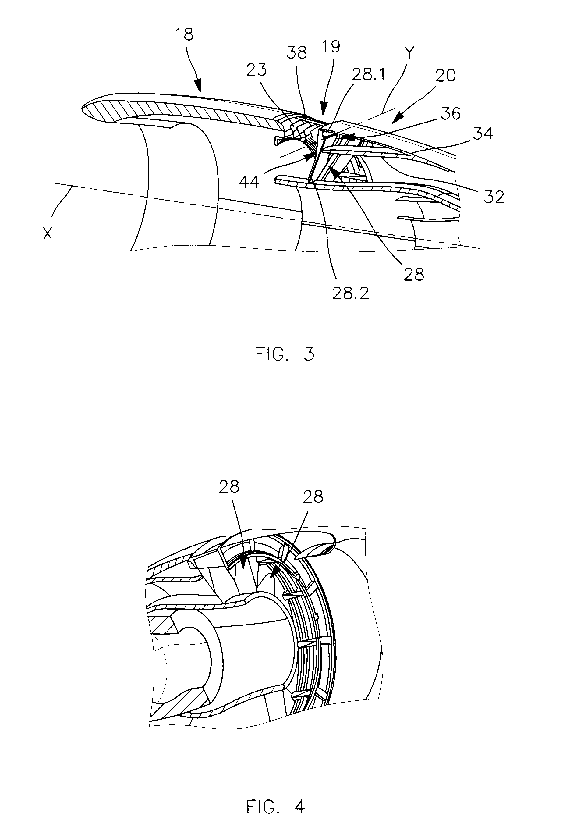
[0029]FIG. 3 is a perspective view of the demi-nacelle in FIG. 2, on which a single flap is shown in deployed position,

[0030]FIG. 4 is a perspective view of the nacelle of the first embodiment viewed from the front, several flaps being shown in deployed position,

[0031]FIG. 5A to 5D are detailed views of the nacelle according to the first embodiment of this invention representing different positions of the thrust reverser, between an inactive position of the thrust reverser towards an active position,

second embodiment

[0032]FIG. 6 is a longitudinal section view of a nacelle according to this invention, with the thrust reverser in inactive position,

[0033]FIG. 7 is a perspective view of the demi-nacelle of FIG. 6 on which a single flap is shown in deployed position,

[0034]FIGS. 8A to 8D are detailed views of FIG. 7 under different angles of view, with the flap(s) in deployed position,

[0035]FIGS. 9A to 9F are detailed views of the nacelle according to the second embodiment of this invention representing different positions of the thrust reverser, between an inactive position of the thrust reverser towards an active position.


PUM


Abstract

Aircraft nacelle comprising a cowling and an engine, the cowling comprising a fixed portion and a mobile portion able to slide in order to define a radial opening with the mobile portion, a thrust reverser system comprising a plurality of flaps intended to be deployed in order to seal at least partially an annular channel surrounding the engine, the mobile portion of the cowling comprising an annular housing extending longitudinally in order to receive the flaps in rest position. Each flap is linked to the fixed portion by a pivot joint and is linked to the mobile portion by a sliding-pivot joint, in such a way that a sliding of the mobile portion in separating from the fixed portion provokes a rotation of each flap around the axis of rotation of the joint with the fixed portion.

Description

TECHNICAL FIELD AND PRIOR ART[0001]This invention relates to an aircraft nacelle, and more particularly to a device provided on an aircraft nacelle in order to reduce, cancel or reverse the thrust produced by a propulsion unit.[0002]An aircraft propulsion unit comprises an engine with on the one hand, a fan comprising a rotor provided with blades and a stator provided with vanes, and on the other hand, a primary duct wherein are arranged according to the direction of air flow, stages of compressors, a combustion chamber and stages of turbines. The engine is arranged in a nacelle which comprises upstream of the fan an air inlet and downstream of the stator of the fan a secondary duct.[0003]Generally, the secondary duct has substantially the form of an annular channel surrounding the primary duct. The primary duct is lined to the wing by a longitudinal pylon serving to fix the propulsion unit to the wing, crossing the annular channel, and linked to an upper portion of the primary duct...

Claims


Application Information

Patent Timeline
Patent Type & Authority Applications(United States)
IPC IPC(8): F02K1/62
CPCF02K1/72F05D2260/96Y02T50/671Y02T50/60
Inventor ANDRE, ROBERTLETAY, BENOITSAGET, BENJAMININGHELBRECHT, ERIC
Owner AIRBUS OPERATIONS (SAS)
Why Eureka
Try Eureka