

Expanders for lead-acid batteries
- Summary
- Abstract
- Description
- Claims
- Application Information
AI Technical Summary
Benefits of technology
Problems solved by technology
Method used
Image

Examples
example 1
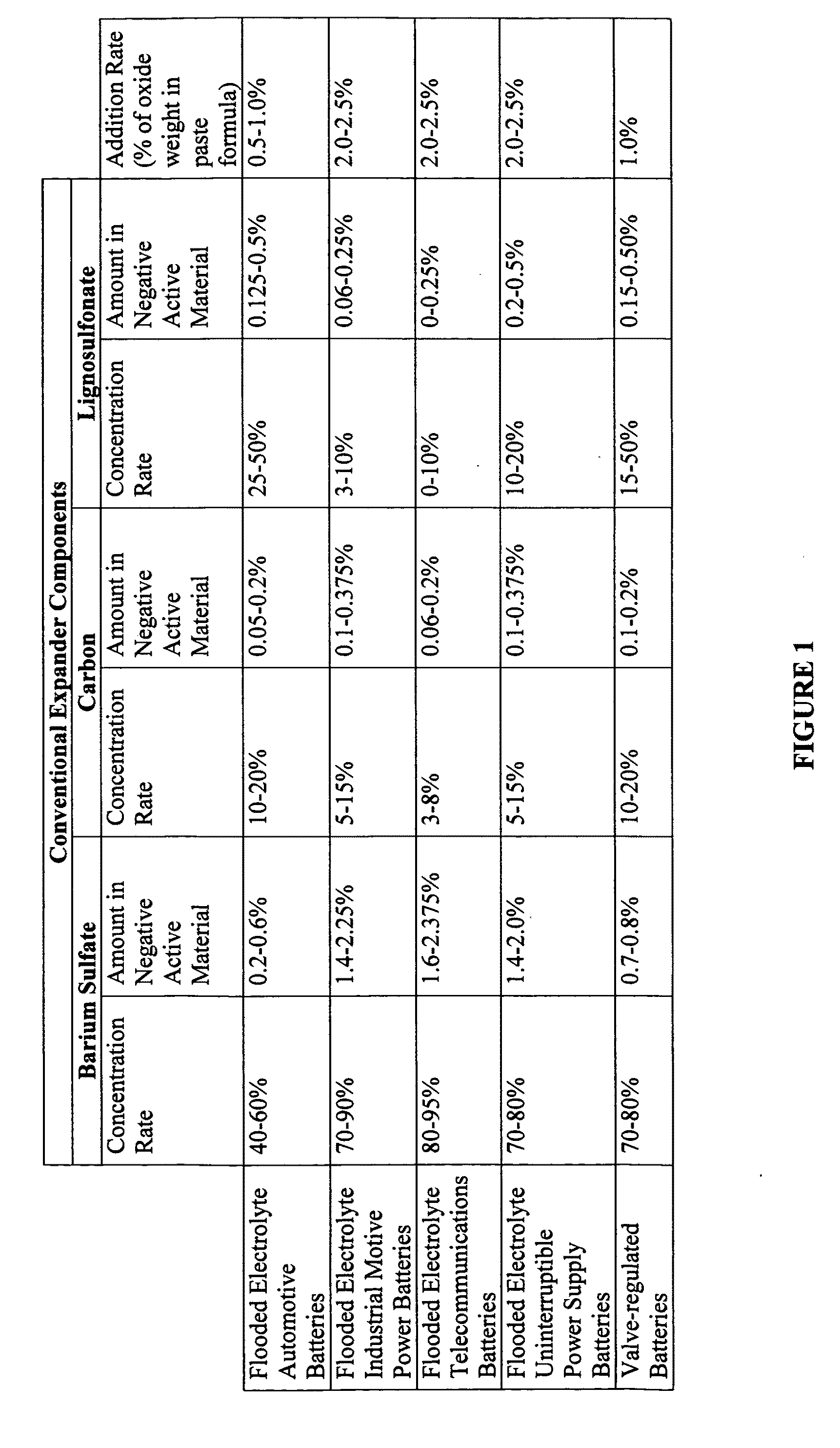
[0036]Example 1 illustrates an example of an effective expander additive having the composition of 8 kg of barium sulfate, 6 kg of lignosulfonate, preferably sodium lignosulfonate, 20 kg of carbon black and 20 kg of graphite. When added to a typical negative paste batch produced from 1000 kg of leady oxide, this yields a negative plate with 0.8% of barium sulfate, 0.6% of sodium lignosulfonate, 2.0% carbon black and 2.0% of graphite, i.e., 4% mixture of carbon black and graphite. All of the aforementioned percentages are of the oxide used in the paste batch. It should be understood that this is a preferred example composition and that other amounts and ratios will also produce the beneficial results of the present disclosure.
[0037]Lead-acid battery cells having a capacity of 1.74 Ampere-hours were made from negative plates using this expander formulation of Example 1, and compared to cells using a conventional expander blend comprising 8 kg of barium sulfate, 3 kg of lignosulfonate ...
example 2
[0038]Example 2 illustrates another example of an effective additive having the composition 8 kg of barium sulfate, 2 kg of lignosulfonate, preferably sodium lignosulfonate, and 20 kg of graphite. When added to a typical negative paste batch produced from 1000 kg of leady oxide, this yields a negative plate with 0.8% of barium sulfate, 0.2% of sodium lignosulfonate and 2.0% of graphite. All of the aforementioned percentages are of the oxide used in the paste batch. It should be understood that this is a preferred example composition and that other amounts and ratios will also produce the beneficial results of the present disclosure.
[0039]Lead-acid battery cells having a capacity of 1.74 Ampere-hours were made from negative plates using this expander formulation of Example 2, and compared to cells using the conventional expander blend described above with respect to Example 1. The cells were tested according to the simulated hybrid electric vehicle test schedule described above with ...
example 3
[0040]Example 3 illustrates yet another example of an effective expander additive having the composition 8 kg of barium sulfate, 2 kg of lignosulfonate, preferably sodium lignosulfonate, 20 kg of carbon black and 20 kg of graphite. When added to a typical negative paste batch produced from 1000 kg of leady oxide this yields a negative plate with 0.8% of barium sulfate, 0.2% of sodium lignosulfonate, 2.0% of carbon black and 2.0% of graphite, i.e., 4% mixture of carbon black and graphite. All of the aforementioned percentages are of the oxide used in the paste batch. It should be understood that this is a preferred example composition and that other amounts and ratios will also produce the beneficial results of the present disclosure.
[0041]Lead-acid battery cells having a capacity of 1.74 Ampere-hours were made from negative plates using this expander formulation of Example 3, and compared to cells using the conventional expander blend described above with respect to Example 1. The c...
PUM
 Abstract
Description
Claims
Application Information