
Bur for Adjustable Tool Drive Arrangement

a technology of drive arrangement and adjustable tool, which is applied in the direction of boring tools, turning tools, dental tools, etc., can solve the problems of time-consuming and cost-intensive, not designed to allow for length adjustment of tools, and repeated tool changes

Inactive Publication Date: 2009-12-31
TTI TURNER TECH INSTR
View PDF25 Cites 10 Cited by
  • Summary
  • Abstract
  • Description
  • Claims
  • Application Information

AI Technical Summary

Benefits of technology

[0010]It is an object of the present invention to obviate or mitigate at least one disadvantage of prior art handpiece designs.
[0012]In a preferred embodiment, the tool includes a maximum retraction indicator for indicating to a user when the tool has been retracted to the maximum retraction position. This provides a significant advantage over the prior art by allowing a user to adjust the exposed length of a rotatable tool, preferably a dental bur, without exceeding safe operating limits.
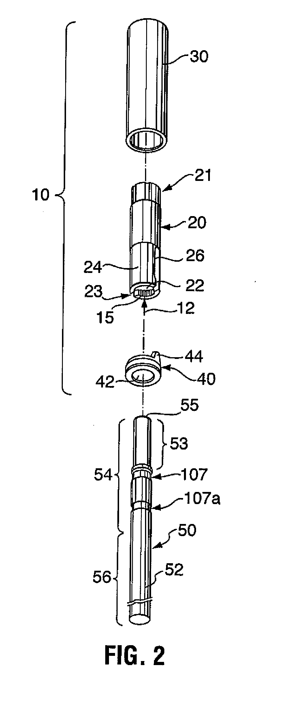
[0018]In one variant, the contact surface is a detent on the driven portion and the stop is an axial end shoulder of the detent. In a particularly preferred embodiment, frictional engagement of an elongated detent by the tool retaining member allows the tool to be positioned in the handpiece at any insertion depth between the minimum insertion depth (or maximum extraction depth) and the maximum insertion depth. In another variant, the tool comprises two or more detents on the driven portion, each having a stop shoulder for axial engagement with the tool engaging member for defining one or more intermediate insertion depths between the minimum tool insertion depth and the maximum retraction depth. In a particularly preferred embodiment, the detent is a groove extending circumferentially about the driven portion of the tool.
[0021]It is a significant advantage, of an adjustable length tool drive arrangement and tool in accordance with the invention allowing axial adjustment of tool insertion depth in a dental handpiece, that the number of times a dentist must exchange tools for selection of different tool lengths during the course of a dental procedure is reduced. This reduces the time required to perform the procedure and can reduce operating cost, since fewer tools of specific length need to be purchased and maintained. It is another significant advantage that, by providing the preferred maximum retraction indicator, excessive wear and damage due to insufficient insertion of the tool in the handpiece and the concomitant loss of concentricity are avoided.
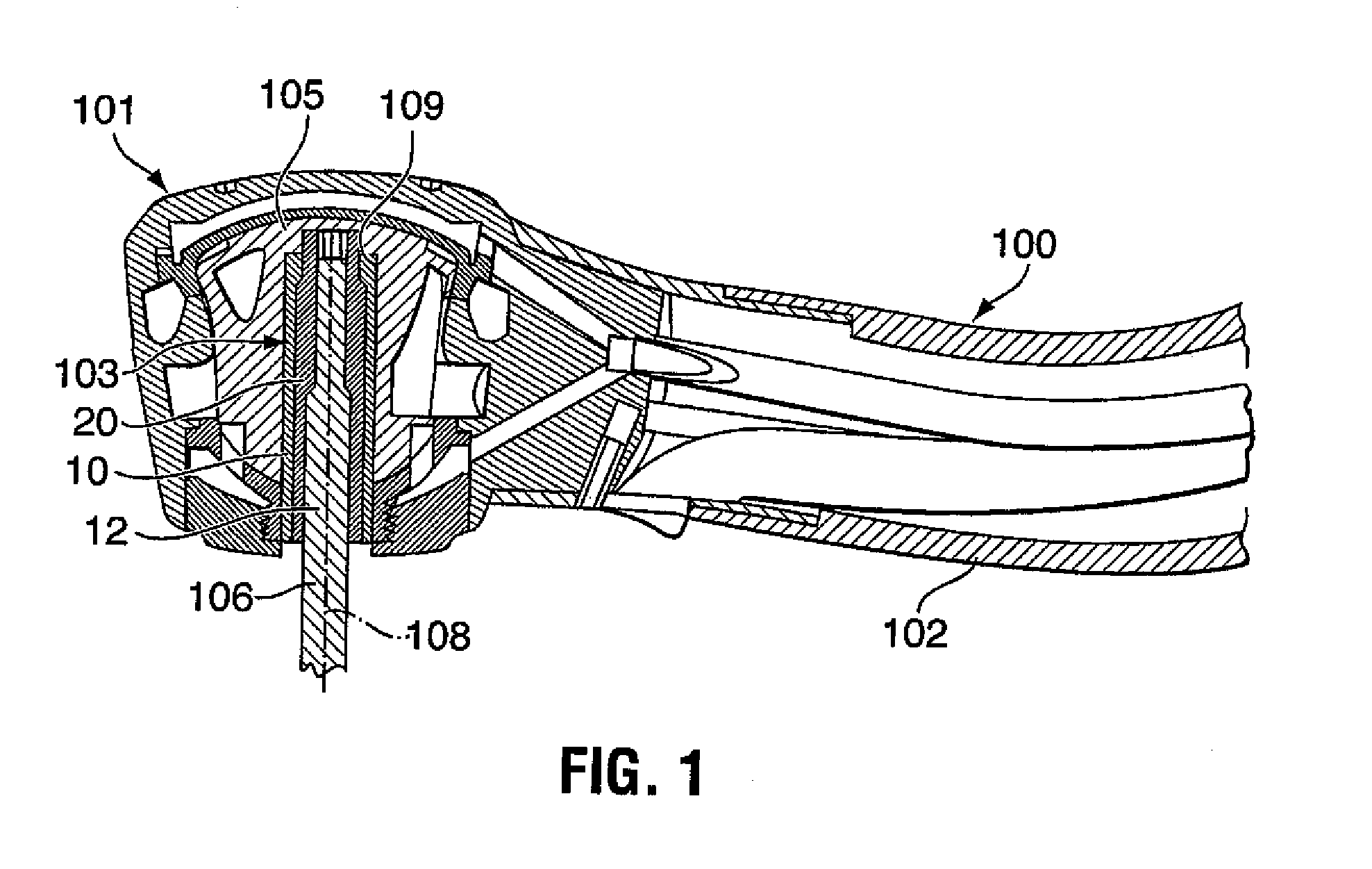
[0023]Tools in accordance with the invention are intended for use with a handpiece chuck which is a generally cylindrical member having a tool receiving axial bore. A portion of the wall surrounding the bore is resiliently deformable and forms the resilient tool engaging member to allow insertion of the driven portion of the tool into the bore. When the tool is inserted, the chuck wall portion forming the tool engaging member radially inwardly engages the driven portion to frictionally retain the tool in the bore. Axial engagement of the tool engaging member with a first stop shoulder on the contact surface of the tool provides a maximum tool retraction indication. The resilient wall portion of the chuck may form of a pair of diametrically opposed axially extending retaining arms, or friction grip arms, at least one of which has a radially inwardly projecting protrusion extending therefrom for frictionally engaging the contact surface of the tool and for axially engaging a mechanical retraction depth indicator on the tool, such as the maximum retraction depth indicator. The chuck may further include a ram for selectively forcing apart the retaining arms to allow insertion and / or removal of the tool. Various tool drive arrangements are contemplated in accordance with the present invention, which can allow for torque transfer from the drive directly to the rotatable tool.

Problems solved by technology

The known drive arrangements are not designed to allow for length adjustment of the tool, which means the tool, once fully inserted in the drive arrangement will always protrude the same length from the drive head.
However, as a dental procedure progresses, a dentist may need to use dental tools of different length.
This creates the need for repeated tool changes, which is time consuming and cost intensive, since a collection of different length tools must be purchased.
However, this adjustment is made without knowledge whether the bur will remain properly engaged within the drive mechanism and safely secured within the drive head.
This is a dangerous practice, since prior art handpieces are not designed to hold the bur in any position other than fully inserted into the drivehead.
However, concentrical support of the tool within the drive head and reliable torque transmission from the drive to the tool are not ensured.
However, those friction arms are somewhat flexible by design and generally do not provide sufficient force to maintain the rear end of the tool concentrically aligned in the drive when lateral forces are applied to the working end of the tool during use.
Therefore, operation of a conventional handpiece at a tool Insertion depth other than fully inserted can result in loss of concentricity, vibration of the bur during rotation, excessive wear, damage to the drive assembly, permanent deformation of the tool securing mechanism and drive spindle components, inefficient torque transfer, increased bur slippage (both rotational and axial), and most dangerously, accidental disengagement of the bur from the handpiece during use.
Only low torque transmission is possible between the chuck and the bur in such constructions, higher torque leading to slippage of the bur.
At the high rotational speeds achieved by modern dental handpieces, bur slippage, in both the axial and rotational directions, can become a problem.
Rapid deceleration of the bur can also lead to rotational slippage, for example, when the drive continues to rotate while the bur is locked or snagged.
Friction between the drive assembly and the dental bur during rotation leads to significant wear of both elements over time.
This friction can also produce significant heat, as can friction generated in push-button lock handpieces when the user maintains pressure on the push-button during operation.
Friction heat can cause permanent damage to the drive spindle components, especially the flexible friction arms of the chuck, which are normally made of heat tempered material.
The damage can lead to rotational slippage and even axial slippage of the tool, possibly resulting in an accidental release of the tool from the handpiece.
Accidental release of a dental bur during high speed rotation can pose a threat to both the patient and the dentist.
Continued wear of the bur and drive assembly during operation necessitates routine maintenance and repair of expensive handpiece components.

Method used


Image

  • Bur for Adjustable Tool Drive Arrangement
  • Bur for Adjustable Tool Drive Arrangement
  • Bur for Adjustable Tool Drive Arrangement

Examples


Embodiment Construction

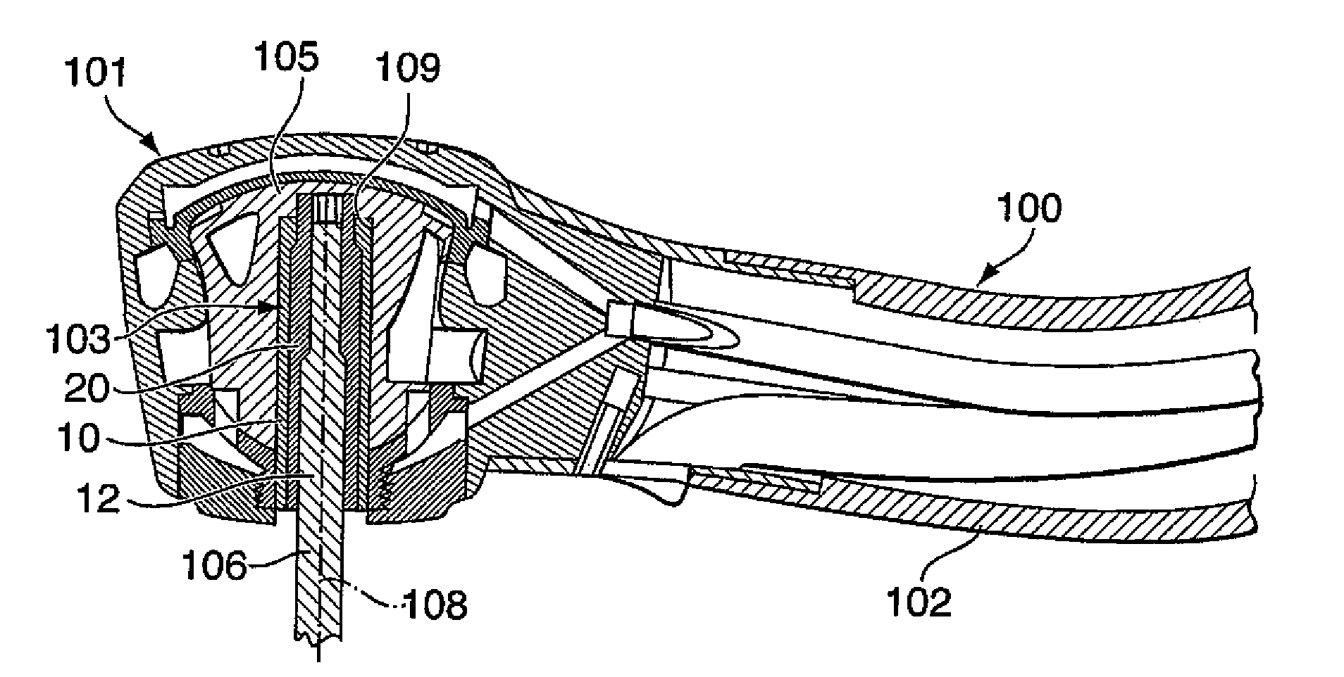
[0045]Generally, the present invention provides a tool drive arrangement for a handpiece with a drive head, the tool drive arrangement permitting length adjustment of a tool in the drive head by concentrically supporting the tool in the drive head at any position from a fully inserted position to a maximum retracted position.

[0046]In one embodiment, the invention provides a tool drive assembly including the tool drive arrangement, a rotatable tool and a rotatable tool supporting element for concentrically supporting the tool from the fully inserted position to the maximum retracted position. The tool preferably includes a maximum retraction indicator for indicating to a user when the tool has been retracted to the maximum retraction position. This provides a significant advantage over the prior art by allowing a user to adjust the exposed length of a rotatable tool, preferably a dental bur, without exceeding safe operating limits.

[0047]More particularly, the rotatable tool drive ass...


PUM


Abstract

The invention relates to an improved dental tool drive arrangement for a handpiece with a drive head, the tool drive arrangement permitting length adjustment of the tool in the drive head by concentrically supporting the tool in the drive head at any position from a fully inserted position to a maximum retracted position. The tool drive arrangement preferably includes a tool and a rotatable tool supporting element for concentrically supporting the tool from the fully inserted to the maximum retracted position, the tool preferably including a maximum retraction indicator for indicating to a user when the tool has been retracted to the maximum retraction position. This provides a significant advantage over the prior art by allowing a user to adjust the exposed length of a rotatable tool, preferably a dental bur, without exceeding safe operating limits. The invention also relates to an improved drive spindle which allows depth adjustment of a tool in a dental handpiece while maintaining efficient torque transfer and concentricity during high speed rotation.

Description

CROSS-REFERENCE TO RELATED APPLICATION[0001]This application is a continuation application of U.S. application Ser. No. 11 / 921,860, filed Dec. 10, 2007, which represents a National Stage application of PCT / CA2006 / 000954 filed on Jun. 9, 2006 entitled “Adjustable Dental Tool Drive Arrangement” and is a continuation-in-part of U.S. patent application Ser. No. 11 / 262,959, entitled “Adjustable Tool Drive Arrangement”, filed Nov. 1, 2005 and claims the benefit of U.S. Provisional Patent Application Ser. No. 60 / 689,052, entitled “Dental Burr And Drive Spindle”, filed Jun. 10, 2005, which applications are included herein by reference in their entirety.FIELD OF THE INVENTION[0002]The present invention relates generally to handpieces for rotating tools. More particularly, the present invention relates to an improved drive arrangement for a rotatable tool and the tool.BACKGROUND OF THE INVENTION[0003]Numerous handpieces for rotating tools exist. Turbine driven handpieces are widely used in de...

Claims


Application Information

Patent Timeline
Patent Type & Authority Applications(United States)
IPC IPC(8): A61C1/14
CPCA61B17/162A61C1/141A61C1/144B25G1/005A61C3/02B23B31/005B23B2260/0487A61C1/145
Inventor BAILEY, KEVIN JOHNMILLSON, ANDREW DOUGLASTURNER, DEREK M.J.CASTONGUAY, JEAN
Owner TTI TURNER TECH INSTR
Learn More