
Reusable core carbon-carbon composite brake disc

a carbon-carbon composite and brake disc technology, applied in the direction of braking discs, friction linings, paper/cardboard containers, etc., can solve the problems of carbon-carbon composites that cannot be manufactured only slowly, cost of raw materials, maintenance costs, etc., and achieve high heat capacity and high heat capacity

Inactive Publication Date: 2010-01-07
HONEYWELL INT INC
View PDF17 Cites 36 Cited by
  • Summary
  • Abstract
  • Description
  • Claims
  • Application Information

AI Technical Summary

Benefits of technology

[0016]The present invention provides an improved method of manufacturing a carbon-carbon composite brake disc comprising a dense reusable core. Preferably, the reusable core has a density of from 1.8 g / cc to 2.05 g / cc. The method of this invention includes the steps of: forming a dense carbon-carbon composite core; positioning the dense core in a location within a carbon-carbon composite brake disc; and fixing (e.g., by molding, riveting, or adhering) the dense carbon-carbon composite core in place in its location within the carbon-carbon composite brake disc. More particularly, this manufacturing method may include the steps of: forming a dense carbon-carbon composite core with high heat capacity; positioning the dense core in a mold; and forming a carbon-carbon composite brake disc preform around the core in said mold. Alternatively, this manufacturing method may include the steps of: forming a carbon-carbon composite brake disc preform having a cavity located therein; forming a dense carbon-carbon composite core with high heat capacity; positioning the dense core into the cavity in the carbon-carbon composite brake disc preform; and fixing the core in the cavity in said carbon-carbon composite brake disc preform. It is economically advantageous if the dense core is recovered from a worn brake disc prior to positioning it in the brake disc.
[0017]Thus, another aspect of this invention is a method of lowering the cost of manufacturing carbon-carbon composite brake discs over a series of manufacturing runs. In this method, the basic steps are: (a) forming a dense carbon-carbon composite core with high heat capacity; (b) positioning the dense core in a location within a carbon-carbon composite brake disc; (c) fixing the dense carbon-carbon composite core in place in its location within the carbon-carbon composite brake disc; (d) recovering the dense carbon-carbon composite core from a worn brake disc; and (e) repeating steps (b) and (c) with a core recovered in step (d). Generally, in this aspect of the invention, the step of repeating step (e) is itself repeated one or more times.

Problems solved by technology

Two major cost areas associated with aircraft brakes are the initial cost, which includes raw material costs and the cost (for energy, etc.) of manufacturing process steps, and maintenance costs, including the need to replace the friction material due to wear.
Carbon-carbon composites can be manufactured only slowly—it can take up to four months to complete the manufacturing process.
Accordingly, the cost of the material is necessarily high.
Also, carbon-carbon composites generally are subject to significant wear during taxiing.
Aircraft brakes are subjected to high temperatures in use.
The temperature at which a carbon-carbon composite brake can operate is limited by the ability of surrounding structures (e.g., hydraulic piston assembly, wheel, and tire) to withstand the temperature generated by the carbon-carbon heat sink and also by the tendency of carbon-carbon composites to oxidize at higher temperatures, weakening the carbon-carbon composite structures.
This may lead to failure of the brakes to provide sufficient torque to stop the aircraft.
Also, the amount of energy that must be absorbed to stop the aircraft during landing increases with the increase in size and speed of the aircraft.

Method used


Image

  • Reusable core carbon-carbon composite brake disc
  • Reusable core carbon-carbon composite brake disc
  • Reusable core carbon-carbon composite brake disc

Examples


example 1

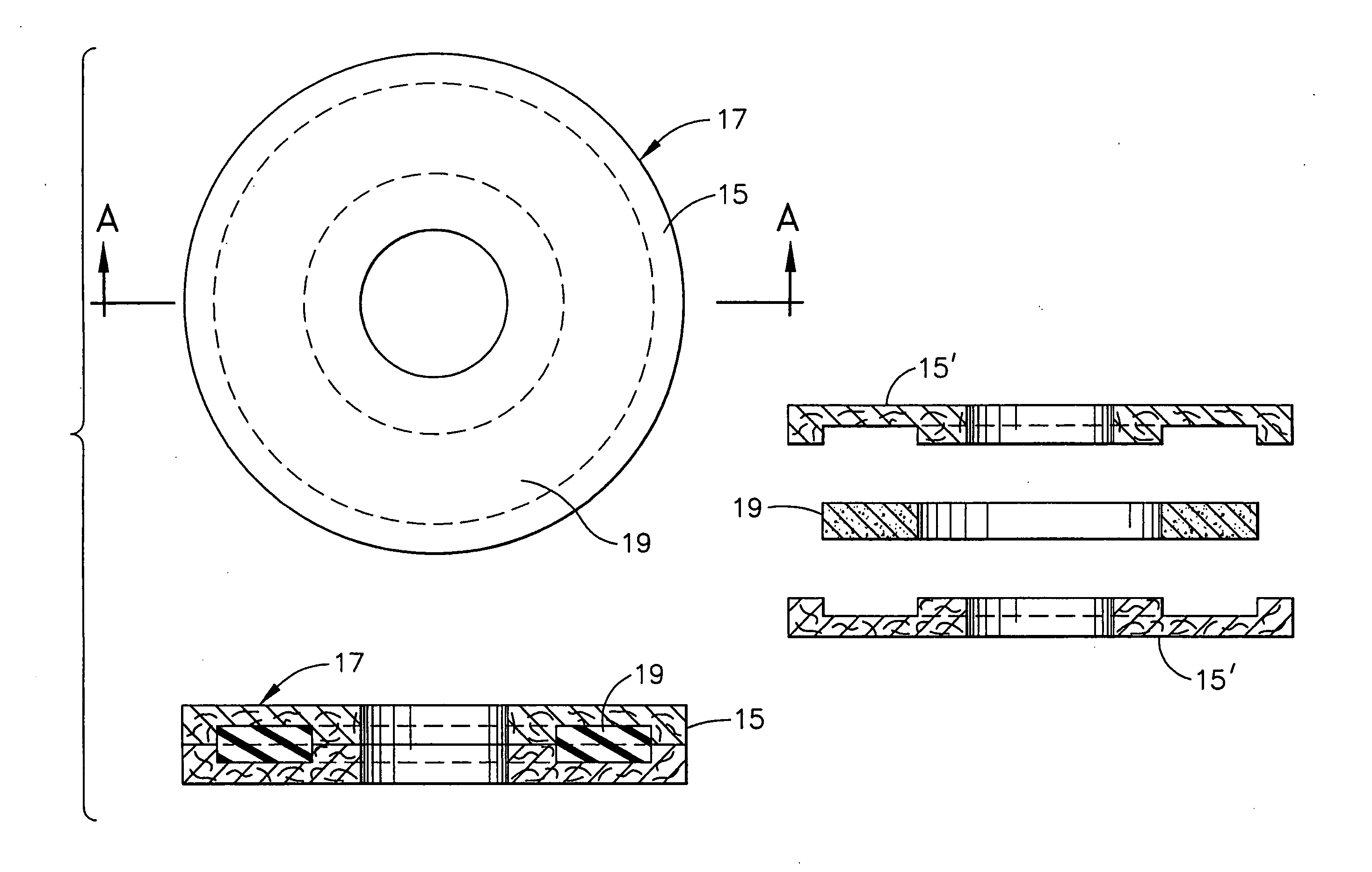
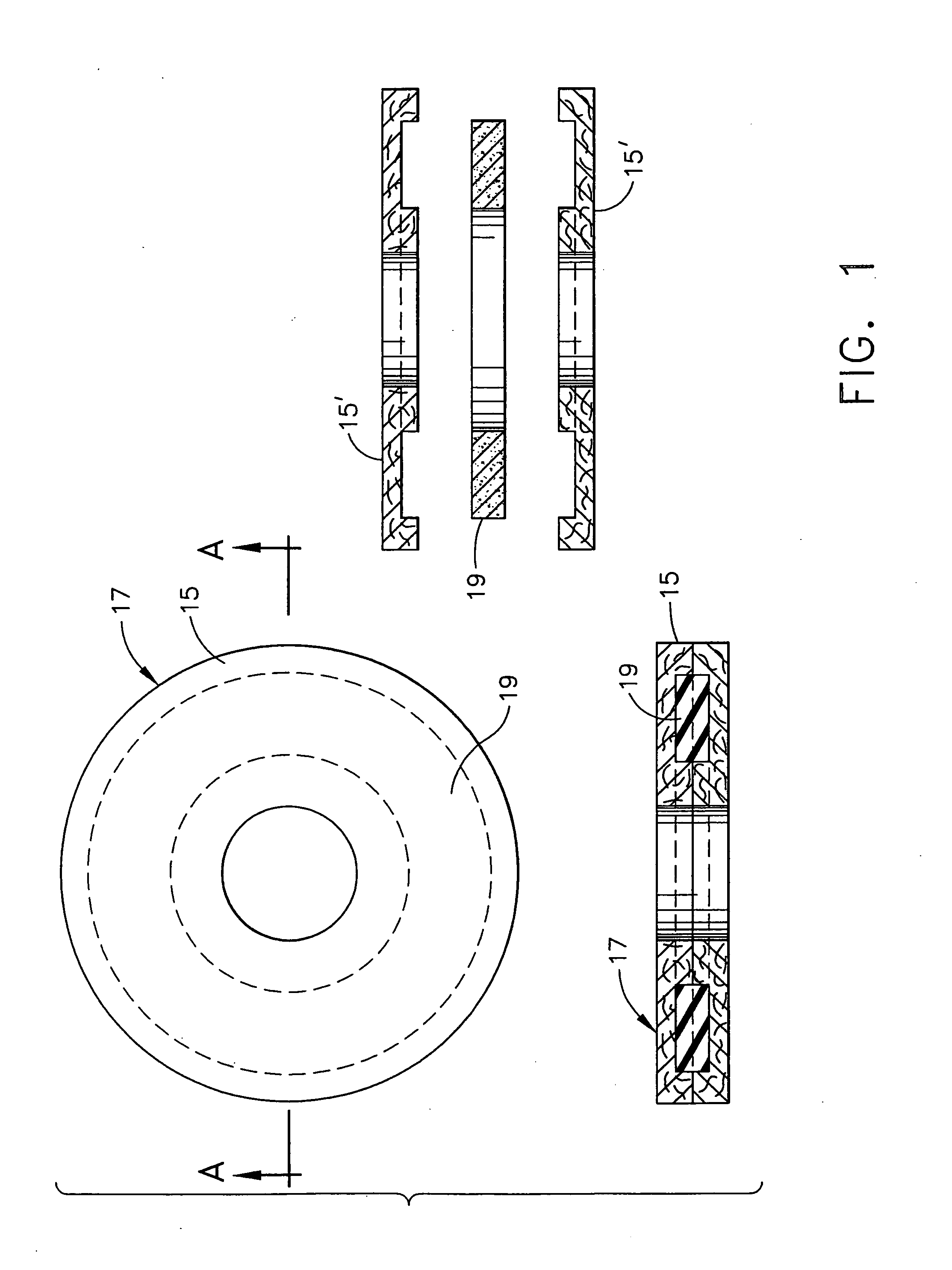
[0045]In a typical but non-limiting process, 40 parts by weight of chopped polyacrylonitrile fibers are sprayed into an annular heat sink core mold to provide a matrix of fibers in the mold. The mold is configured with an internal ring-shaped space having an external diameter of 18 inches, an internal diameter of 9 inches, and a thickness of 1 inch. Twenty parts by weight of phenolic resin binder in powder form is simultaneously sprayed into the mold. The resulting fibrous matrix containing binder is compressed, and the binder is cured, providing a preform matrix. The preform matrix is infliltrated with pitch to form a pitch matrix. The pitch matrix is subjected to Chemical Vapor Infiltration to form a high heat capacity carbon-carbon composite core.

example 2

[0046]In an alternative method for forming a core for use in accordance with the present invention, a standard nonwoven fabric-based preform is densified to about 2 g / cc. The highly densified preform is then machined to a desired size and used as a core in a brake disc.

example 3

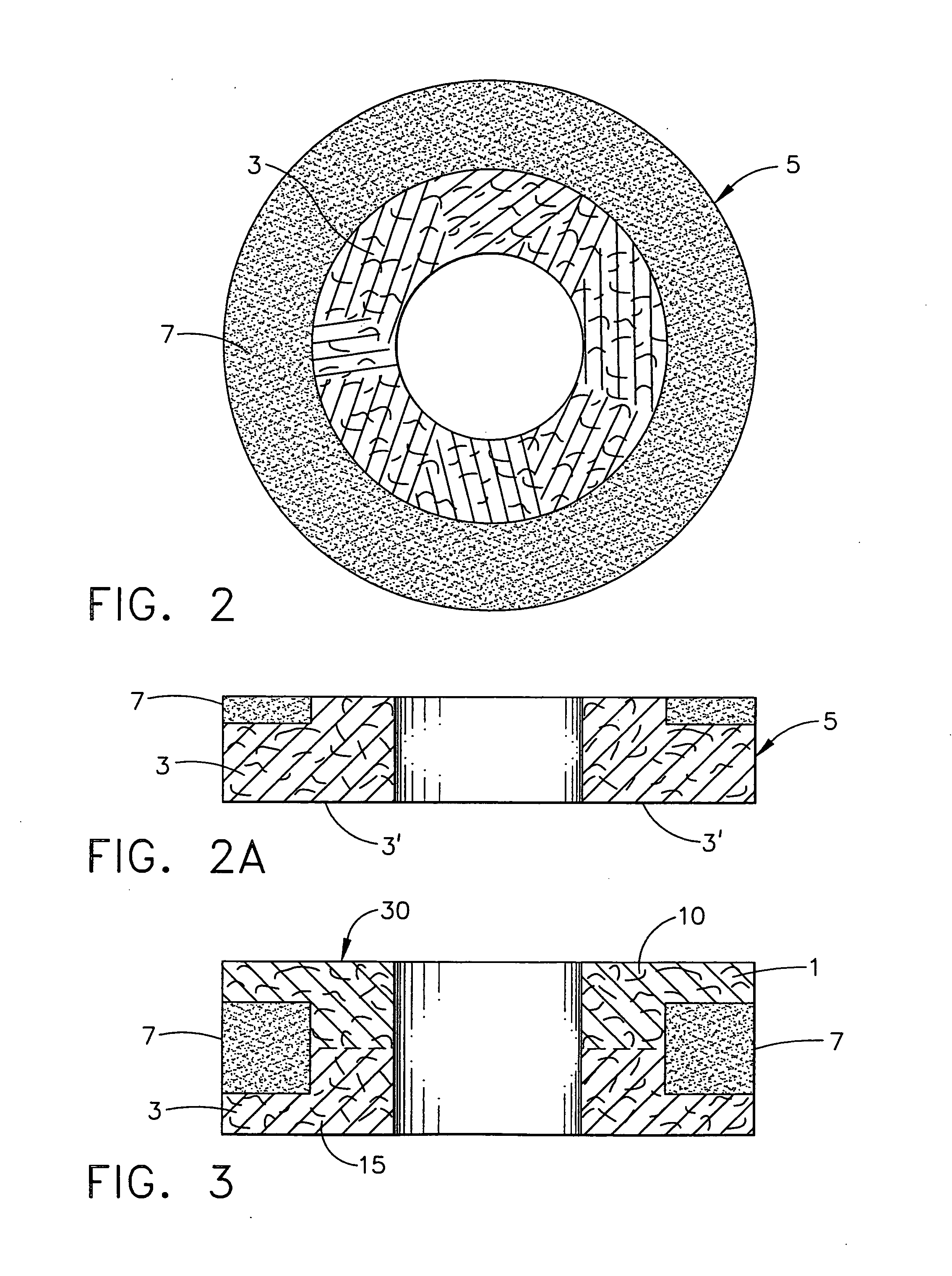
[0047]The reusable core preform manufactured in this way is placed in an annular brake stator disc mold configured with an internal ring-shaped space having an external diameter of 18 inches, an internal diameter of 6 inches, and a thickness of 3 inches. Sixty-five parts by weight of chopped polyacrylonitrile fibers are sprayed into the annular brake stator disc mold to provide a matrix of fibers in the mold and 35 parts by weight of phenolic resin binder in powder form is simultaneously sprayed into the mold. The resulting fibrous matrix containing binder is compressed, and the binder is cured, providing a preform matrix. The preform matrix is filled with pitch to form a pitch matrix. The pitch matrix is subjected to CVI and / or to an additional pitch infiltration step to form a carbon-carbon composite brake disc preform.


PUM

PropertyMeasurementUnit
Densityaaaaaaaaaa
Densityaaaaaaaaaa
Densityaaaaaaaaaa

Abstract

Method of manufacturing carbon-carbon composite brake disc comprising a dense reusable core. Preferably, the reusable core has a density of 1.8-2.05 g / cc. The method includes: forming a dense carbon-carbon composite core; positioning the dense core in a location within a carbon-carbon composite brake disc; and fixing the dense carbon-carbon composite core in place in its location within the carbon-carbon composite brake disc. It is economically advantageous to recover the dense core from a worn brake disc prior to positioning it in the brake disc. Also, an annular carbon-carbon composite brake disc made up of a friction surface containing 15-75 weight-% carbon-containing fibers and 25-85 weight-% resin binder and a dense carbon-carbon composite core comprising 40-75 weight-% carbon-containing fibers and 25-60 weight-% resin binder.

Description

CROSS-REFERENCE TO RELATED APPLICATION[0001]This application claims priority under 35 U.S.C. §119(e) to provisional application Ser. No. 60 / 558,112, which was filed on Apr. 1, 2004. The disclosure of Ser. No. 60 / 558,112 is incorporated herein by reference.FIELD OF THE INVENTION[0002]This application relates to carbon-carbon composite brake discs and to methods of manufacturing them. Preferred embodiments of the present invention contemplate carbon-carbon composite brake discs employed in aircraft landing systems.BACKGROUND OF THE INVENTION[0003]Carbon-carbon composite friction materials are used in aircraft brakes due to their high heat capacity, their ability to function as a friction material and their resistance to oxidation at elevated temperatures. Carbon-carbon composite brakes have various components including rotors, stators, backing plates, and pressure plates, all of which may be made of carbon-carbon composite friction materials.[0004]Two major cost areas associated with ...

Claims


Application Information

Patent Timeline
IPC IPC(8): B21J15/00B32B37/02F16D65/00F16D65/12F16D69/00F16D69/02F16D69/04
CPCC04B35/83C04B2235/614C04B2235/616C04B2235/75C04B2235/77F16D65/12Y10T156/10F16D69/04F16D2069/002F16D2069/005F16D2069/0491Y10T29/49956F16D69/023
Inventor LA FOREST, MARK L.FRYSKA, SLAWOMIR T.WAHLERS, CHRISTOPHER S.JOHNSON, DARRELL L.SIMPSON, ALLEN H.
Owner HONEYWELL INT INC
Features
  • Generate Ideas
  • Intellectual Property
  • Life Sciences
  • Materials
  • Tech Scout
  • Unparalleled Data Quality
  • Higher Quality Content
  • 60% Fewer Hallucinations
Learn More