Method for repairing flexible tube

a flexible tube and repair technology, applied in the field of flexible tube repair, can solve the problems of repair material peeling off, abrasion and scratches on the jacket, and the surface irregularities of the top coat layer, and achieve the effect of preventing the surface irregularities of the repaired flexible tub

Active Publication Date: 2010-01-07
FUJIFILM CORP
View PDF14 Cites 15 Cited by
  • Summary
  • Abstract
  • Description
  • Claims
  • Application Information

AI Technical Summary

Benefits of technology

[0011]According to the method for repairing the flexible tube of present invention, the repair material is applied to the damaged area and then the damaged area is covered with the repair tube to make the surface of the repair material flush with the surface of the jacket, and thereafter the repair material is hardened. As a result, surface irregularities of the repaired flexible tube are prevented.

Problems solved by technology

Such handling causes abrasion and scratches on the jacket, which may be developed into a damaged area such as a hollow.
In the methods described in the above publications, No. 2006-218107 and No. 2005 / 0203337 A1, the repair material may be projected like edges from the surface of the top coat layer and hardened, resulting in surface irregularities of the top coat layer.
A force to pull the snagged gauze may cause the repair material to peel off.
This may mislead a cleaning operator to think of the repaired area as a defect.

Method used


Image

  • Method for repairing flexible tube
  • Method for repairing flexible tube
  • Method for repairing flexible tube

Examples


Embodiment Construction

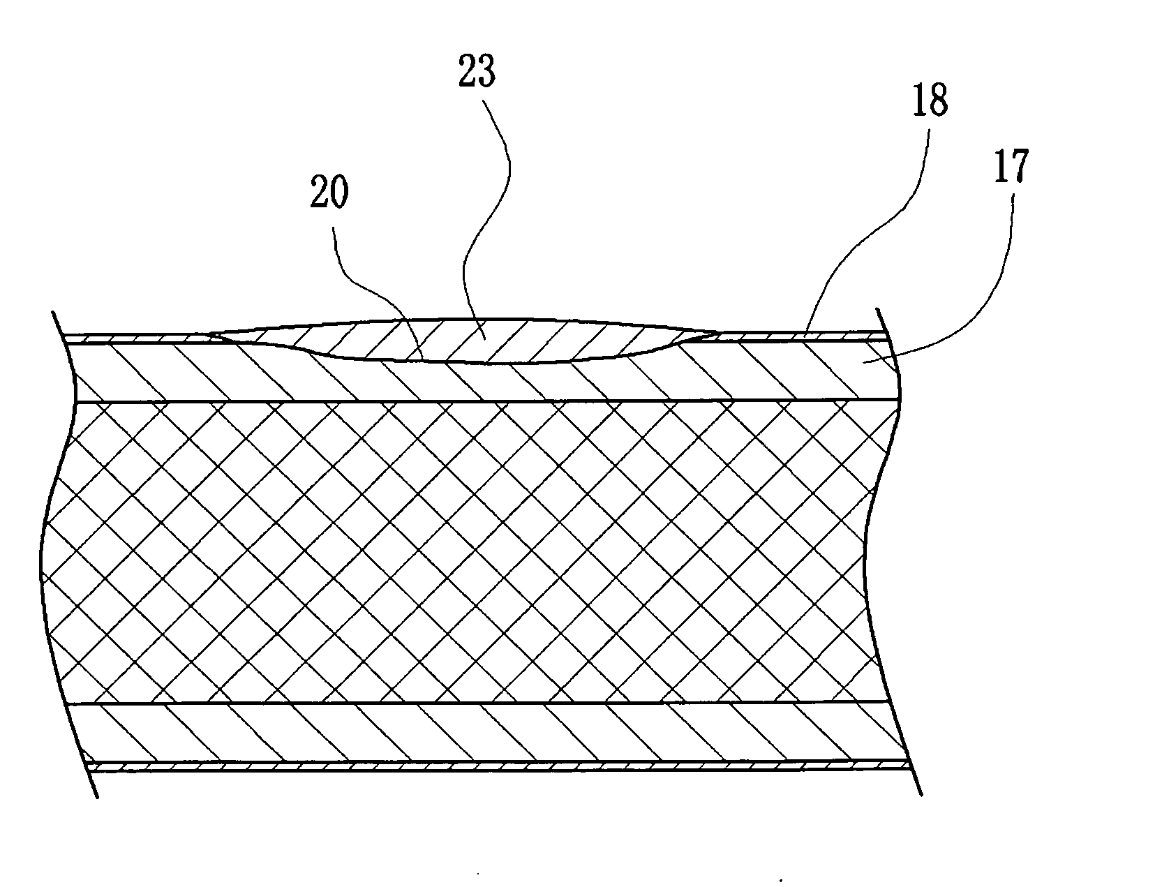
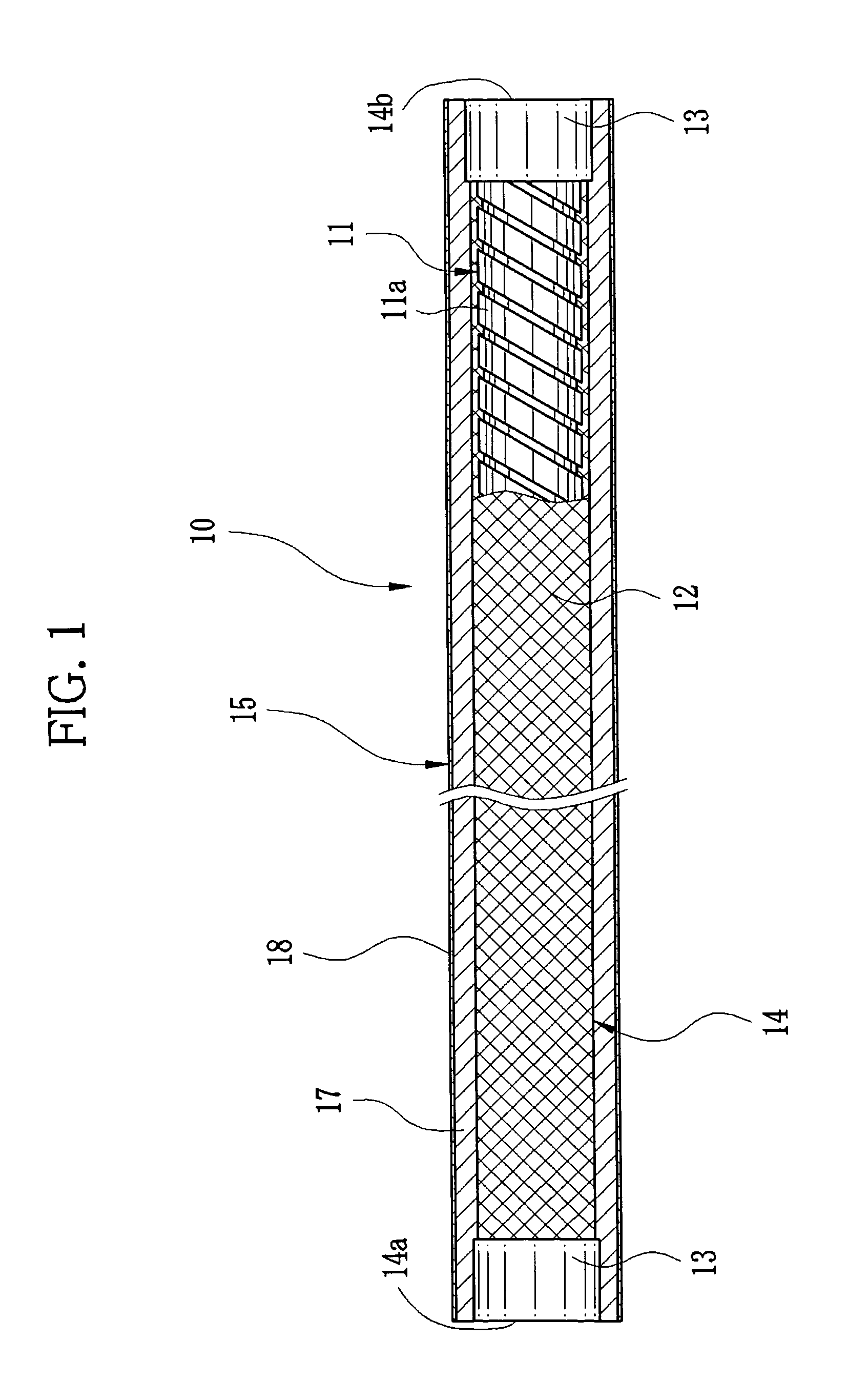
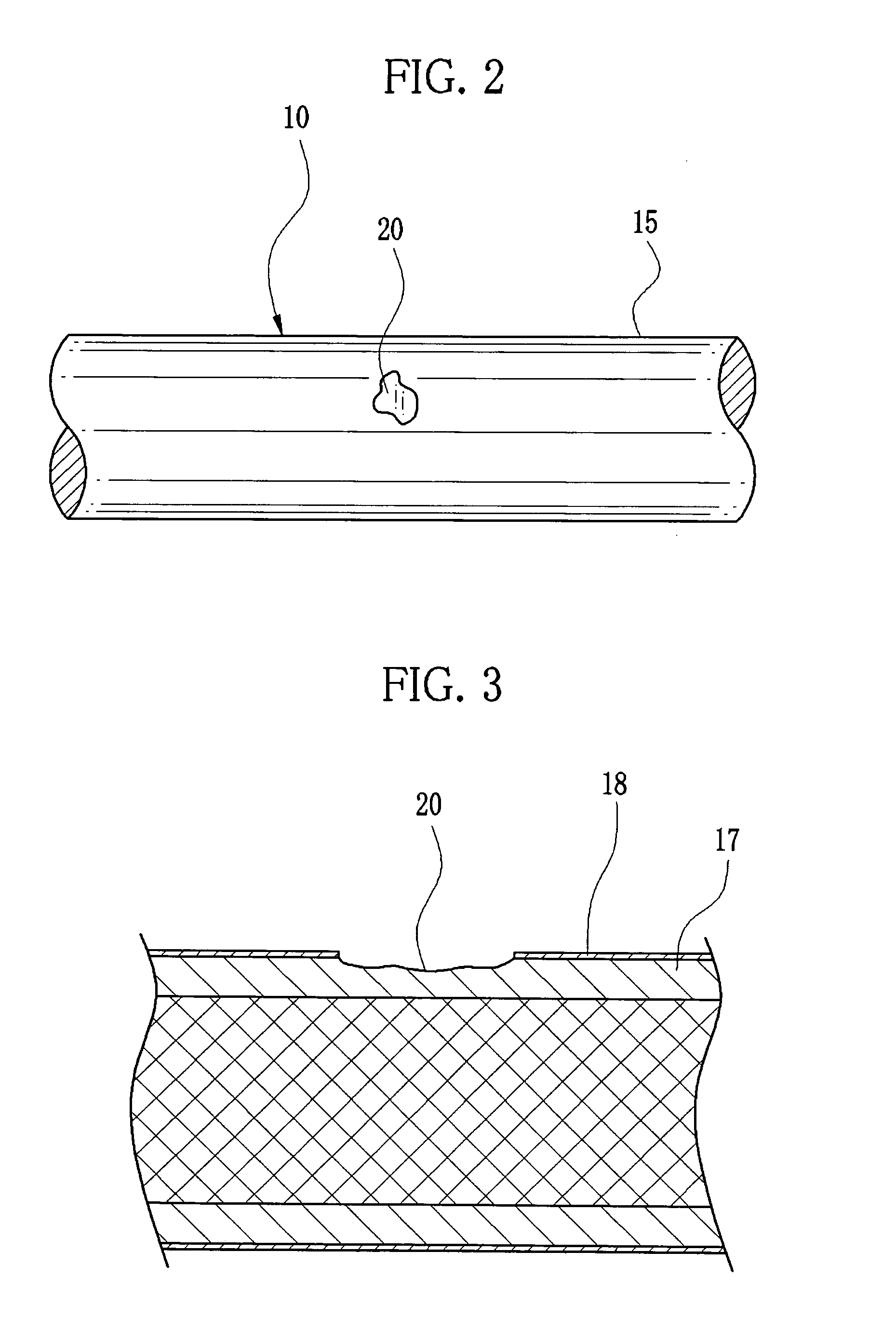
[0027]In FIG. 1, a flexible tube 10 is constructed of a flexible tube structure 14 and a jacket 15 formed on a circumferential surface of the flexible tube structure 14. The flexible tube structure 14 includes a spiral tube 11, a tube-like mesh 12, and a pair of end rings 13. The spiral tube 11 is a metal band 11a wound in a helical fashion. The tube-like mesh 12 is a braided metal wire wrapping around the spiral tube 11. The pair of end rings 13 retains the spiral tube 11 and the tube-like mesh 12. Numerals 14a and 14b indicate openings of the flexible tube 10.

[0028]The jacket 15 includes a polymer layer 17 and a top coat layer 18. The polymer layer 17 is formed on the circumferential surface of the flexible tube structure 14. The top coat layer 18 is formed on the polymer layer 17. The top coat layer 18 contains, for example, acrylic polyol as a main component. The polymer layer 17 is made of thermoplastic elastomer.

[0029]The flexible tube 10 is an essential part of an insert sect...


PUM


Abstract

Around a damaged area of a jacket of a flexible tube, a top coat layer whose adhesion to a polymer layer is weak is peeled off with an adhesive tape. The damaged area and its immediate surrounding area are sanded, and then wiped with ethanol for cleaning. A main agent and a hardening agent are heated and defoamed while being mixed to prepare a repair material. The repair material is applied to the damaged area and the immediate surrounding area. A heat shrink tube is opened along slits in an end portion and covers the flexible tube. The heat shrink tube is shrunk with hot air, pressing the repair material and making it flush with a surface of the jacket. The flexible tube is heated with an electric hot plate to harden the repair material. Thereafter, the heat shrink tube is peeled off from the flexible tube.

Description

FIELD OF THE INVENTION[0001]The present invention relates to a method for repairing a flexible tube. More specifically, the present invention relates to a method for repairing a damaged area on a jacket of a flexible tube used in, for example, an endoscope.BACKGROUND OF THE INVENTION[0002]A medical endoscope for observing a body cavity of a patient is known. A flexible tube that is an essential part of an insert section of an endoscope is constructed of a flexible tube structure around which a jacket is formed. This jacket is formed with a thermoplastic layer such as a urethane polymer layer applied to a circumferential surface of the flexible tube structure, and a top coat layer applied to the thermoplastic layer. The flexible tube structure includes a spiral tube and a tube-like mesh. The spiral tube is made of a metal band wound in a helical fashion, and the tube-like mesh wraps around the spiral tube.[0003]The flexible tube is frequently bent or twisted during operation, and the...

Claims


Application Information

Patent Timeline
Patent Type & Authority Applications(United States)
IPC IPC(8): F16L55/16
CPCA61B1/00071A61B1/0011A61B1/005G02B23/2476B05D5/00B05D7/02B05D2254/02B05D1/42
Inventor KAMATA, KOUICHIIWASAKI, ATSUSHIAYAME, DAISUKETAKAHASHI, NOBUHARU
Owner FUJIFILM CORP
Why Eureka
Try Eureka