Pressure relief valve for a hydraulic tensioner

a pressure relief valve and tensioner technology, applied in the field of tensioners, can solve the problems of chain force oscillation, excessive chain force, spring design that requires too much space, etc., and achieve the effect of reducing the oscillation of the relief valve, simple design and less moving parts

Inactive Publication Date: 2010-01-07
SCHAEFFLER TECH AG & CO KG
View PDF16 Cites 27 Cited by
  • Summary
  • Abstract
  • Description
  • Claims
  • Application Information

AI Technical Summary

Benefits of technology

[0009]It is the object of the Invention to reduce the oscillation of the relief valve during opening and to prove a simpler design with fewer moving parts. It is also the objects of the Invention to provide a relief valve that opens at a higher pressure while reducing the size and weight of the relief valve.
[0016]When the pressure in the hole against the center area of the spring exceeds the preset valve, the spring flexes inward allowing the closed center area to lift off and unseal the hole and for fluid to leak through the hole and the slots in the spring. When the pressure in the hole against the center area of the spring is at or below the preset valve, the flex in the spring seals the hole due to the closed center area pressing against the hole and prevents fluid moving through the hole.

Problems solved by technology

When the crankshaft drives the camshafts, both crankshaft driving power and camshaft loads from the valve trains are oscillatory and cause the chain forces to oscillate.
For some engine operation conditions, the pressure in the chamber can be excessively high and cause excessively high chain force.
Also, for high relief pressure, the spring designs require too much space.

Method used


Image

  • Pressure relief valve for a hydraulic tensioner
  • Pressure relief valve for a hydraulic tensioner
  • Pressure relief valve for a hydraulic tensioner

Examples


Embodiment Construction

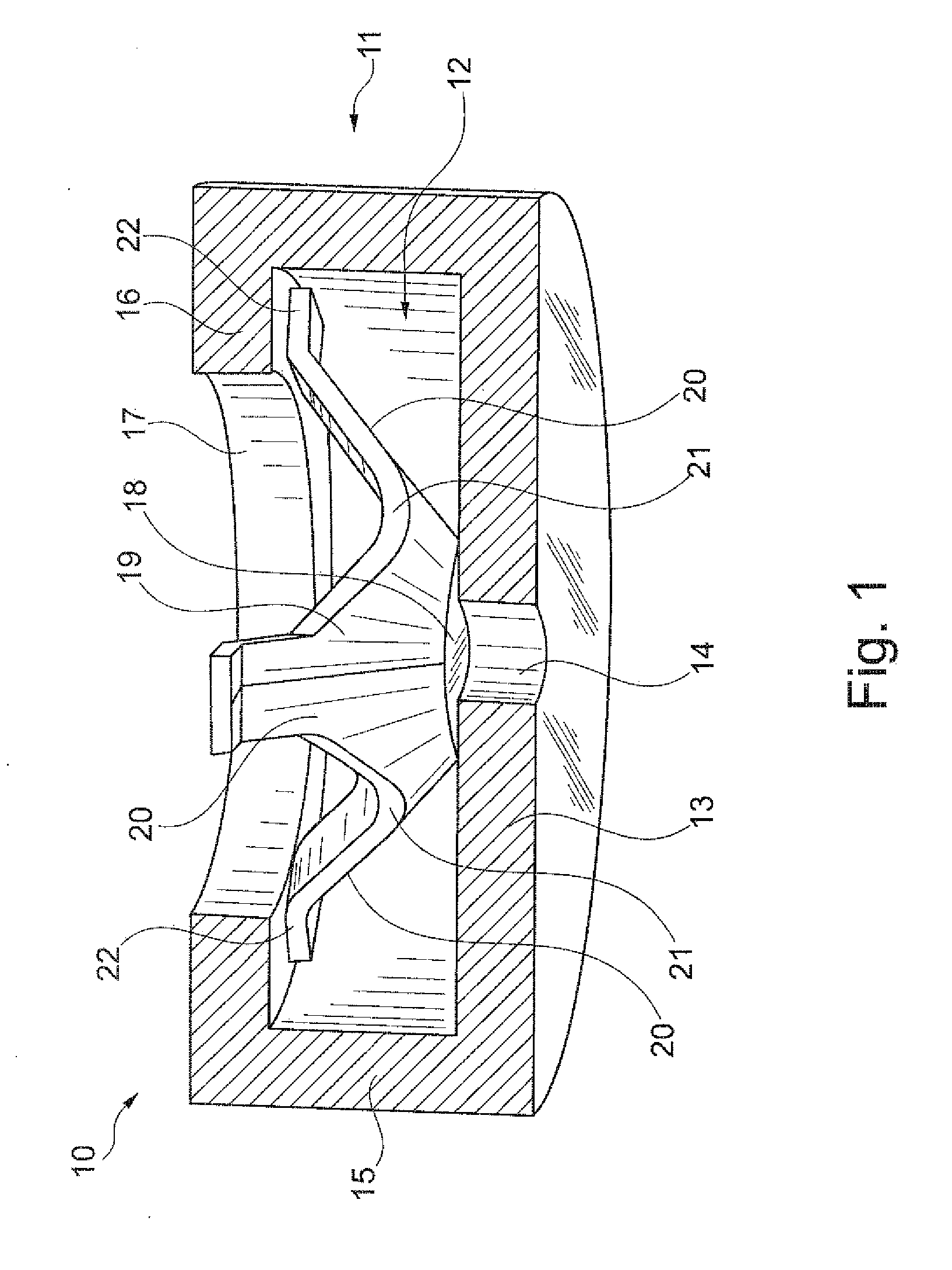
[0039]FIG. 1 illustrates relief valve 10 of the present Invention. Relief valve 10 has cage 11 and slotted Belleville spring 12 prestressed therein. Cage 11 has a bottom wall 13 and a hole 14 centered within bottom wall 13. Side wall 15 of cage 11 extends upward from bottom wall 13. Top wall 16 has an opening 17. Top wall 16 takes the form of an inward radial ledge extending laterally from side wall 15. Cage 11 has an overall cylindrical shape. The interior of cage 11 also has a cylindrical shape in which spring 12 is housed.

[0040]Spring 12 has a closed center area 18 and side wall 19 which extend upward from center area 18. The overall shape of spring 12 is that of a frustum. Side wall 19 has leg 20 which define slot 21. Slot 21 is generally wedge shaped. Leg 20 terminates in a foot 22 which radially extends outward from leg 20.

[0041]Foot 22 presses against ledge portion of top wall 16 and center area 18 presses against bottom wall 13 to fluidly seal hole 14.

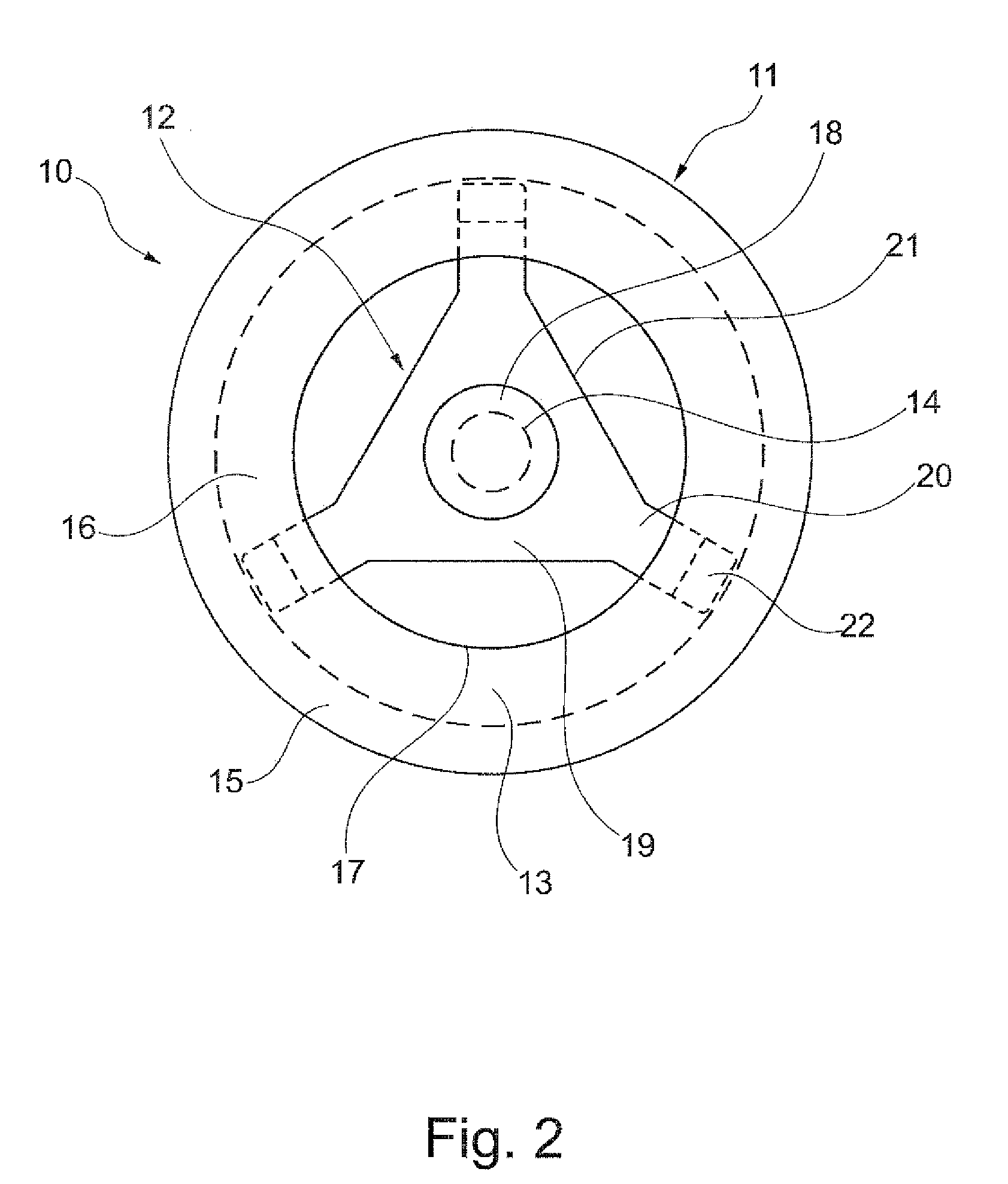
[0042]Turning to FIG. 2...


PUM


Abstract

The relief valve uses a slotted Belleville spring preloaded in a cage. The center area of the spring is closed and presses a hole in the bottom wall of the cage. The top wall of the cage is open and has a ledge against which the radial end of the spring presses. The relief valve is used in a hydraulic tensioner and positioned in the tensioner to have the bottom wall form a wall of the pressure chamber. When the pressure in the pressure chamber exceeds the pressure of the spring against the hole, fluid leaks out of the hole.

Description

FIELD OF THE INVENTION [0001]This Invention relates to tensioners and, more particularly, to hydraulic chain tensioners used in automobiles for timing chains and a pressure relief valve used in the hydraulic chain tensioners.BACKGROUND OF THE INVENTION [0002]Timing chain drives in an automotive engine are endless loops and transmit power from a crankshaft to camshafts. To prevent tooth jump in a chain drive, hydraulic tensioners are applied to provide initial tension in the chain drive. Typically, a hydraulic tensioner works in conjunction with a movable chain guide in the slack side of a chain drive and takes up excess slack in the chain drive to keep the chain in a desired tensioned state. A typical hydraulic tensioner contains a housing with a bore; a hollow piston in the bore forming a pressure chamber; a spring mounted in the bore to push the piston outwards; and a check valve. The check valve provides pressurized supply fluid from an external source of pressurized fluid to the...

Claims


Application Information

Patent Timeline
Patent Type & Authority Applications(United States)
IPC IPC(8): F16H7/08F16K17/04
CPCF16H7/0836F16H2007/0806F16K17/10F16H2007/0814F16K17/0406F16H2007/0812Y10T137/7922
Inventor HE, SIMON XUNNAN
Owner SCHAEFFLER TECH AG & CO KG
Why Eureka
Try Eureka