
Integrated Circuit with Modular Dynamic Power Optimization Architecture

a technology of integrated circuits and dynamic power optimization, applied in the field of power management, can solve the problems of reducing system performance, reducing the clock speed of digital chips, and only being viable, and achieve the effect of reducing power consumption

Active Publication Date: 2010-01-07
AVAGO TECH INT SALES PTE LTD
View PDF14 Cites 14 Cited by
  • Summary
  • Abstract
  • Description
  • Claims
  • Application Information

AI Technical Summary

Benefits of technology

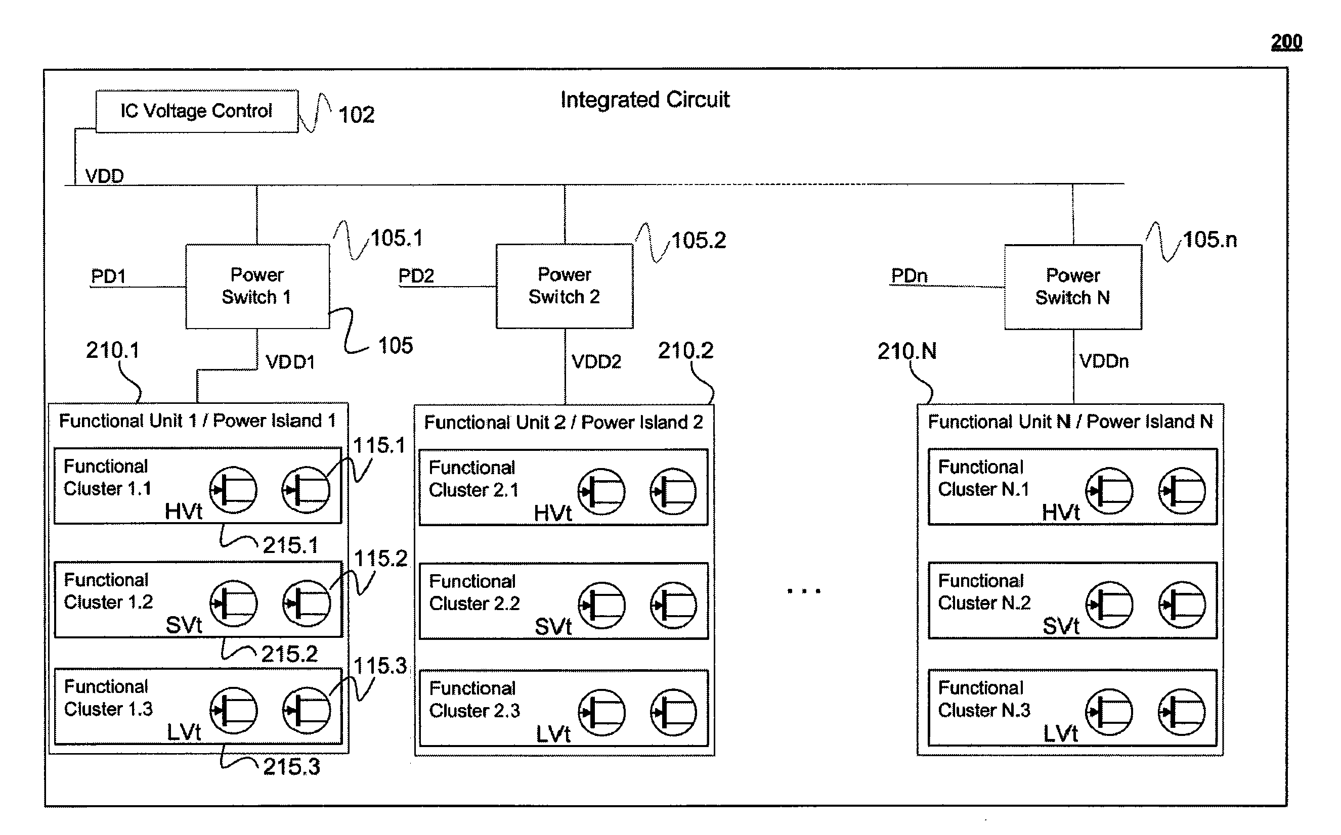
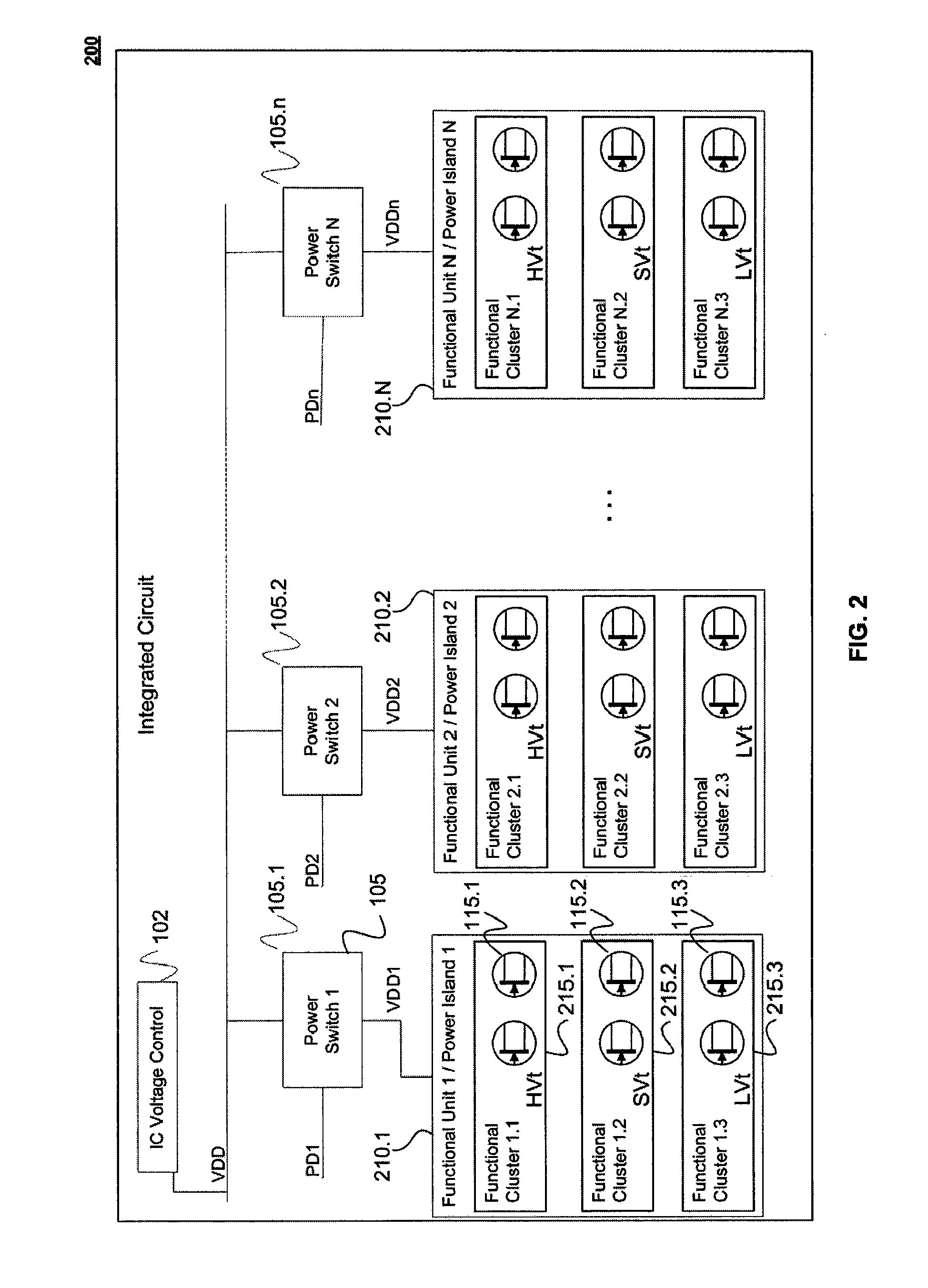
[0008]The present invention meets the above-identified needs by providing a system and method for regulating power consumption within an integrated circuit (IC). In one exemplary embodiment, CMOS transistors are employed, where the CMOS transistors have two or more different threshold voltages, for example, a first threshold voltage and a second threshold voltage. The IC is designed so that any one or more distinct functional modules within the IC utilize only CMOS transistors with a single threshold voltage (for example, only a low threshold voltage or only a high threshold voltage). Consequently, the supply voltage delivered to the distinct functional modules can be lowered to the minimum voltage necessary to enable the transistors within those module to operate.
[0009]Similarly, modules within the IC may be designed with transistors which share a common source for a substrate bias voltage or a clock speed, or with a combination of common values for several electrical factors (supply voltage, substrate bias voltage, clock speed, etc.). In this way, it is possible to reduce power consumption by fine-tuning the voltages supplied to (or clock speeds driving) specific modules in a way which is custom-tuned to each module.

Problems solved by technology

If the module is fed by a single power supply, then this strategy may only be viable if no components or submodules within the module are expected to require power during this period of time.
In virtually all cases, this will result in some kind of reduction in system performance, for example lower clock speeds for digital chips or reduced range for a radio frequency (RF) chip.
For these applications, any attempts at power savings through reduced supply voltages may have a notable impact, and sometimes an unacceptable impact, on system performance in relation to the requirements of the user application.

Method used


Image

  • Integrated Circuit with Modular Dynamic Power Optimization Architecture
  • Integrated Circuit with Modular Dynamic Power Optimization Architecture
  • Integrated Circuit with Modular Dynamic Power Optimization Architecture

Examples


Embodiment Construction

[0022]1. Introduction[0023]2. Definitions[0024]3. Exemplary Integrated Circuit (Conventional)[0025]4. Overview of the Present System and Method[0026]5. Exemplary Integrated Circuit (IC) According to the Present System and Method[0027]6. Another Exemplary IC[0028]7. Another Exemplary IC[0029]8. Another Exemplary IC[0030]9. An Exemplary Method for Designing an IC[0031]10. Exemplary Method for Real Time Dynamic Power Minimization for an IC[0032]11. Alternative Embodiments[0033]12. Conclusion

1. Introduction

[0034]The present invention is directed to systems and methods for using a modular organization of electrical components within an integrated circuit (IC) to minimize IC power consumption while maintaining substantially optimal performance by the IC.

[0035]Some systems or methods may be defined or characterized here in whole or in part by exemplary instances of such systems or methods (for example, by an IC with a particular organization of modules and submodules, or a particular organ...


PUM


Abstract

A system and method for regulating power consumption within an integrated circuit (IC) with a modular design. The IC is designed so that any one distinct functional module within the IC utilizes only transistors with a substantially same or similar critical voltage level, which may for example be the threshold voltage of the transistors. Consequently, the supply voltage delivered to each functional modules can be lowered to the minimum voltage necessary to enable the transistors within the module to operate. Similarly, modules within the IC may be designed with transistors which share a common value for a substrate bias voltage or a clock speed, or with a combination of common values for several electrical factors. In this way, it is possible to reduce power consumption by fine-tuning the voltages supplied to (or clock speeds driving) specific modules, in a way which is custom-tuned to each module.

Description

BACKGROUND OF THE INVENTION[0001]1. Field of the Invention[0002]The present invention pertains to the field of power management in a semiconductor environment. More particularly, the invention pertains to a system and method for adaptive scaling of voltages, clock speeds, and other electrical factors within an integrated circuit in order to dynamically minimize power consumption while maintaining optimum performance.[0003]2. Background Art[0004]For virtually all electronics applications, it is desirable to minimize power consumption. In terms of system design and performance, reduced power consumption results in less heat being generated. This increases system life, reduces requirements for cooling systems. A reduction in power supply requirements also enables smaller, more compact design. Further, any reduction in the power consumed by a circuit component, such as an integrated circuit (IC) or a module within an IC, will improve the performance and reliability of prior circuit stag...

Claims


Application Information

Patent Timeline
Patent Type & Authority Applications(United States)
IPC IPC(8): G06F1/26
CPCY02B60/1285G06F1/3296G06F1/3203Y02B60/1278Y02B60/1282G06F1/3287Y02D10/00
Inventor RAKSHANI, VAFA JAMESKRISHNAN, MUSARAVAKKAM SAMARAM
Owner AVAGO TECH INT SALES PTE LTD
Learn More