System for collecting carbon dioxide in flue gas

Inactive Publication Date: 2010-01-14
MITSUBISHI HEAVY IND LTD +1
View PDF11 Cites 21 Cited by
  • Summary
  • Abstract
  • Description
  • Claims
  • Application Information

AI Technical Summary

Benefits of technology

[0015]It is an object of the present invention to at least

Problems solved by technology

However, at the time of stopping the operation of the CO2 collecting device, unless an operation such as containment of the valve, damper or the like, which closes the interior of the stack or rele

Method used


Image

  • System for collecting carbon dioxide in flue gas
  • System for collecting carbon dioxide in flue gas
  • System for collecting carbon dioxide in flue gas

Examples


first embodiment

[0035]A system for collecting carbon dioxide in flue gas according to the present invention is explained with reference to the drawings.

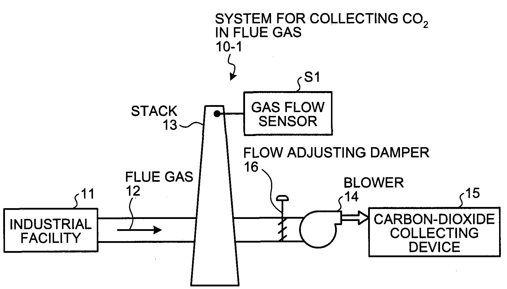
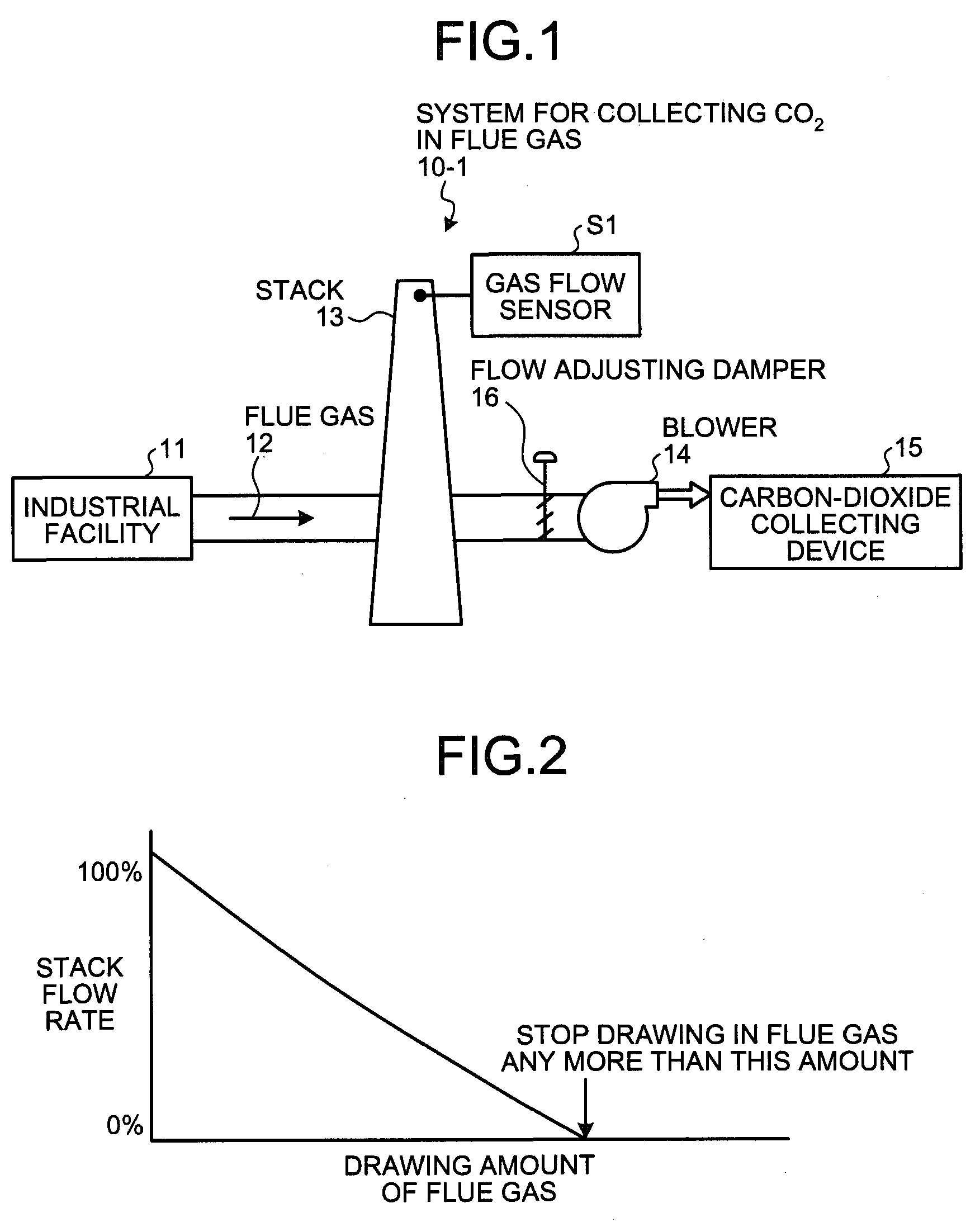
[0036]FIG. 1 is a schematic diagram of the system for collecting carbon dioxide in flue gas according to the first embodiment.

[0037]As shown in FIG. 1, a system for collecting carbon dioxide in flue gas 10-1 according to the first embodiment includes a stack 13 that discharges flue gas 12 discharged from an industrial facility 11 to outside, a blower 14 that is installed at the downstream side of the stack 13 and draws the flue gas 12 therein, a carbon-dioxide collecting device 15 that collects carbon dioxide in the flue gas 12 drawn in by the blower 14, and a gas flow sensor S1 arranged near an exit side within the stack 13. In the gas flow sensor S1, a drawing amount of the flue gas 12 by the blower 14 to the carbon-dioxide collecting device 15 is increased until an exhaust flow rate of the flue gas from the stack 13 becomes zero, and when the dis...

second embodiment

[0044]A system for collecting carbon dioxide in flue gas according to the present invention is explained next with reference to the drawings.

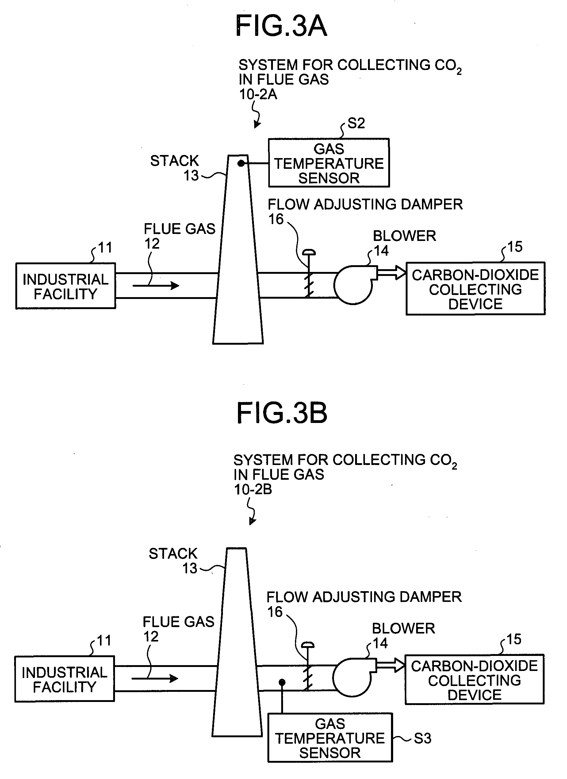
[0045]FIG. 3A is a schematic diagram of the system for collecting carbon dioxide in flue gas according to the second embodiment.

[0046]As shown in FIG. 3A, a system for collecting carbon dioxide in flue gas 10-2A according to the second embodiment includes the stack 13 that discharges the flue gas 12 discharged from the industrial facility 11 to the outside, the blower 14 that is installed at the downstream side of the stack 13 and draws the flue gas 12 therein, the carbon-dioxide collecting device 15 that collects carbon dioxide in the flue gas 12 drawn in by the blower 14, and a gas temperature sensor S2 arranged within the stack 13. In the gas temperature sensor S2, the drawing amount of the flue gas 12 by the blower 14 to the carbon-dioxide collecting device 15 is increased until the gas temperature declines, and when the gas temperature dec...

third embodiment

[0055]A system for collecting carbon dioxide in flue gas according to the present invention is explained next with reference to the drawings.

[0056]FIG. 5A is a schematic diagram of the system for collecting carbon dioxide in flue gas according to the third embodiment.

[0057]As shown in FIG. 5A, a system for collecting carbon dioxide in flue gas 10-3A according to the third embodiment includes the stack 13 that discharges the flue gas 12 discharged from the industrial facility 11 to the outside, the blower 14 that is installed at the downstream side of the stack 13 and draws the flue gas 12 therein, the carbon-dioxide collecting device 15 that collects carbon dioxide in the flue gas 12 drawn in by the blower 14, and an O2 sensor S5 arranged within the stack 13. In the O2 sensor S5, the drawing amount of the flue gas 12 by the blower 14 to the carbon-dioxide collecting device 15 is increased until the oxygen gas concentration is raised, and when the oxygen gas concentration is raised, ...


PUM


Abstract

A system for collecting carbon dioxide in flue gas includes a stack that discharges flue gas discharged from an industrial facility to outside, a blower that is installed at the downstream side of the stack and draws the flue gas therein, a carbon-dioxide collecting device that collects carbon dioxide in the flue gas drawn in by the blower, and a gas flow sensor arranged near an exit side within the stack. A drawing amount of the flue gas by the blower to the carbon-dioxide collecting device is increased until an flow rate of the flue gas from the stack becomes zero in the gas flow sensor, and when the discharged amount of flue gas from the stack becomes zero, drawing in any more than that amount is stopped, and the carbon dioxide in the flue gas is collected while the flue gas is drawn in by a substantially constant amount.

Description

BACKGROUND OF THE INVENTION[0001]1. Field of the Invention[0002]The present invention relates to a system for collecting carbon dioxide in flue gas, capable of stably processing all the carbon dioxide in the flue gas discharged from an industrial facility such as a gas turbine, a furnace, or a boiler.[0003]2. Description of the Related Art[0004]Conventionally, to collect carbon dioxide in flue gas, for example, a system is adopted when an amine-based absorbing solvent is used as a CO2 absorbing solvent to remove and collect CO2 from flue gas; firstly, a process is performed to bring the CO2 absorbing solvent into contact with the flue gas in an absorption column, and thereafter the CO2 absorbing solvent that has absorbed CO2 is heated in a regeneration column; secondly, CO2 is freed and the CO2 absorbing solvent is regenerated, and circulated in the absorption column again, and finally, reused (for example, see Japanese Patent Application Laid-open No. H3-193116).[0005]FIG. 9 is an ...

Claims


Application Information

Patent Timeline
IPC IPC(8): C10J3/82C01B32/50
CPCB01D53/1412B01D53/346B01D53/62B01D2257/504F23J15/006F01N3/20F23J2215/50F23J2900/15061F23L11/00Y02C10/04F01N3/2882F23J15/02Y02C20/40Y02E20/32Y02P20/151
Inventor IIJIMA, MASAKIKAMIJO, TAKASHIYAGI, YASUYUKIOGURA, KOUKI
Owner MITSUBISHI HEAVY IND LTD
Why Eureka
Try Eureka