Selective Catalytic Reduction (SCR) Catalyst Injection Systems

Active Publication Date: 2010-01-14
FORD GLOBAL TECH LLC
View PDF4 Cites 95 Cited by
  • Summary
  • Abstract
  • Description
  • Claims
  • Application Information

AI Technical Summary

Benefits of technology

[0014]In one embodiment, the plate has perforations passing portions of the exhaust gases in the entrance section of the exhaust pipe into the egress section of the exhaust pipe to assist in creating a second impingement between exhaust gas and flows existing from injection conduit outlet and wherein first impingement occurring between exhaust gas entering the conduit through the apertures and reluctant in the conduit.
[0015]In one embodiment, the plate has perforations in an upper portion of the plate between the conduit and an uppe

Problems solved by technology

Selective Catalyst Reduction (SCR) system is proved to be reliable device for NOx reduction; however, the disadvantage of this system is that the ov

Method used


Image

  • Selective Catalytic Reduction (SCR) Catalyst Injection Systems
  • Selective Catalytic Reduction (SCR) Catalyst Injection Systems
  • Selective Catalytic Reduction (SCR) Catalyst Injection Systems

Examples


Embodiment Construction

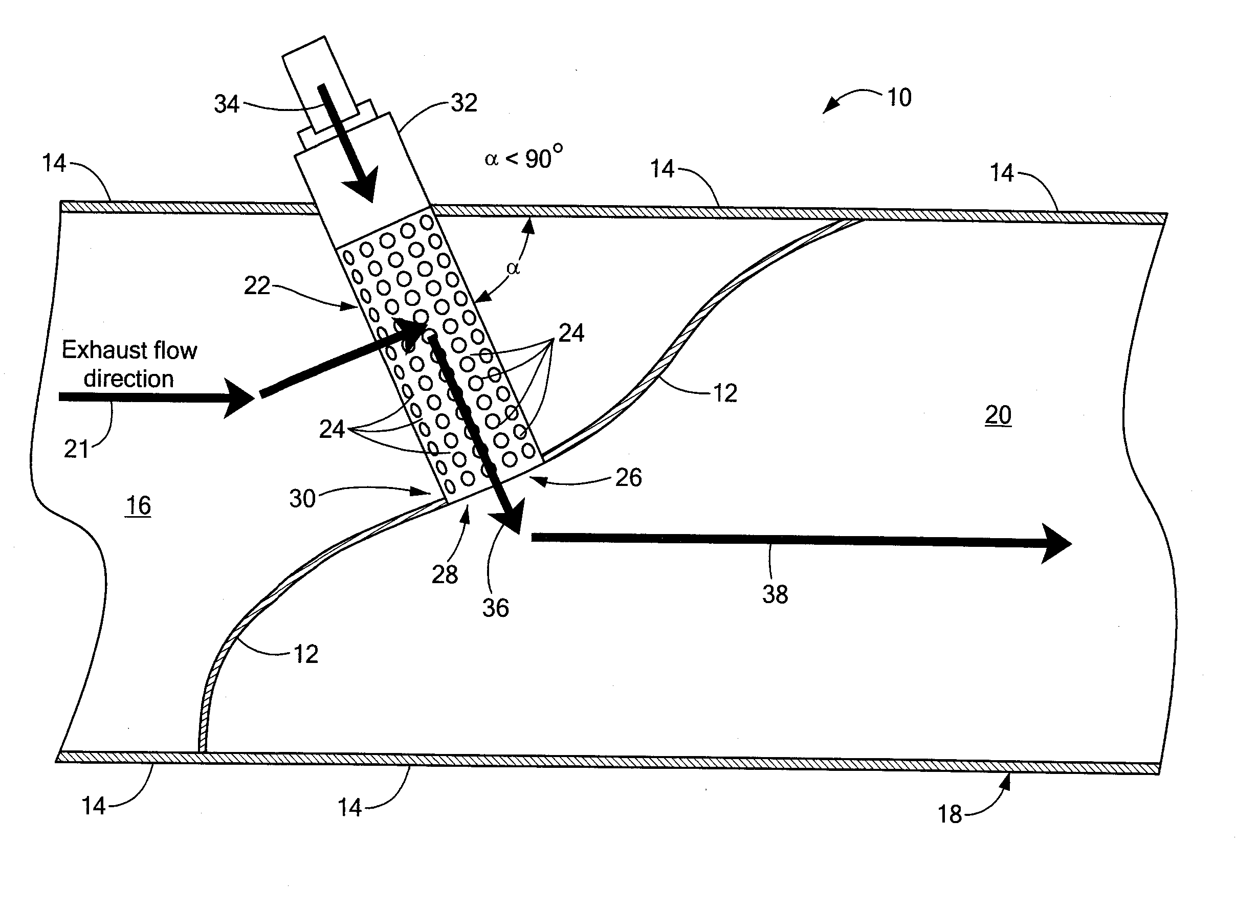
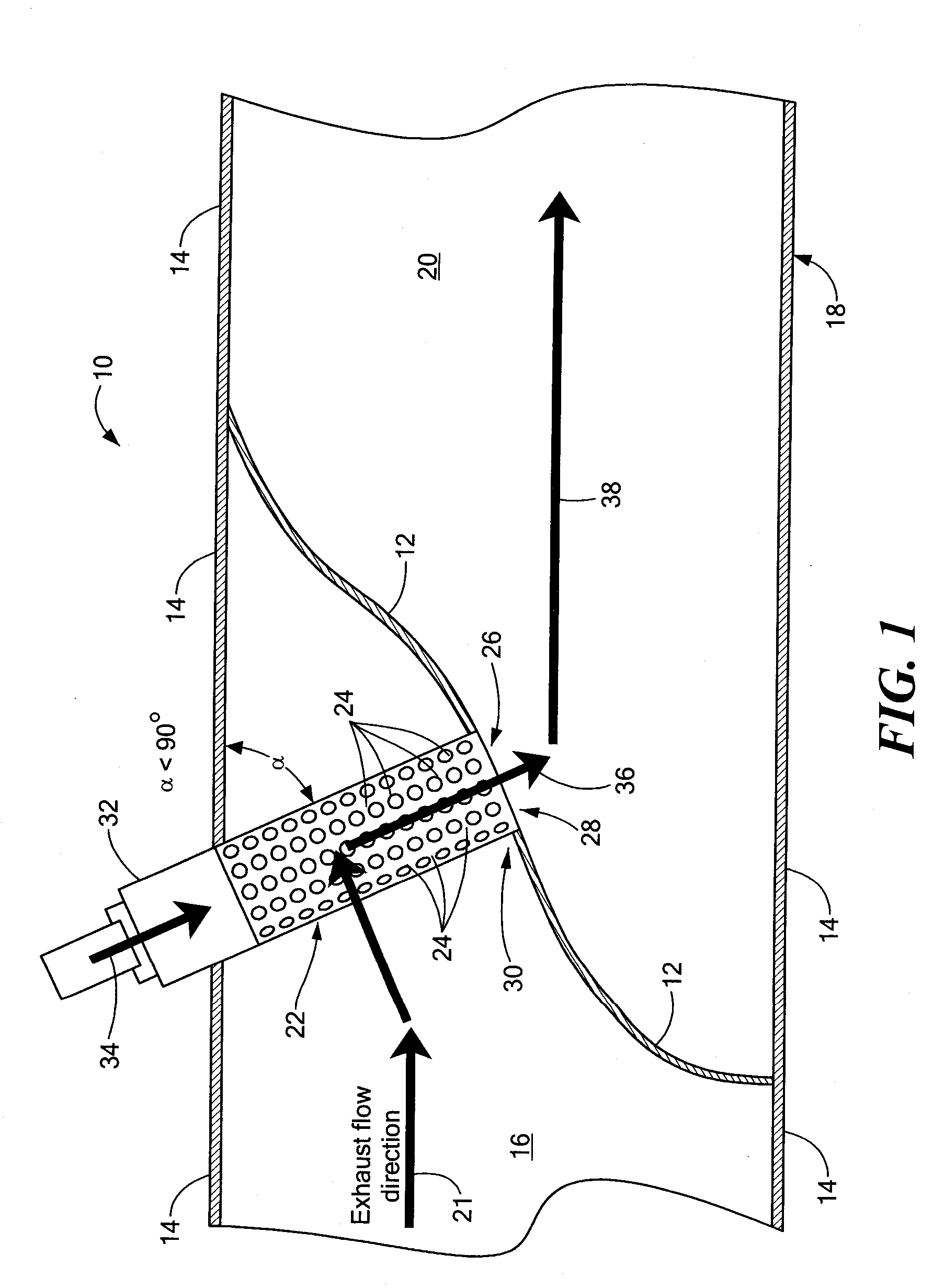
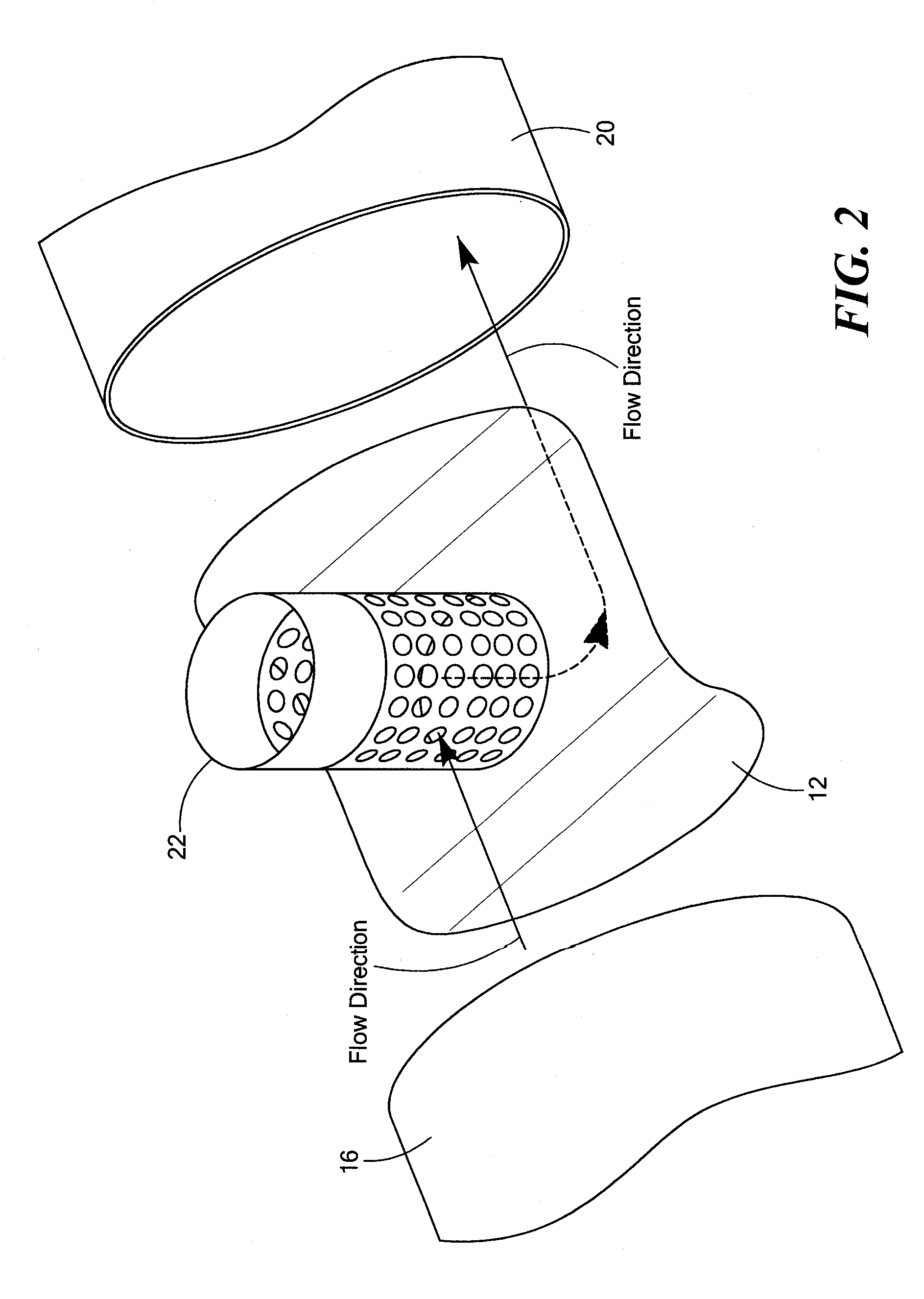
[0028]Referring now to FIGS. 1 and 2, a selective catalytic reduction (SCR) injection system 10 for mixing reductant with exhaust gasses is shown. The system 10 includes: a plate 12 disposed between walls 14 of an entrance section 16 of an exhaust pipe 18, such plate 12 separating such entrance section 16 of the exhaust pipe 18 from an egress section 20 of the exhaust pipe 18; and a reductant-introducing conduit 22. The plate 12 intercepts exhaust gasses, indicated by arrow 21, in the entrance section 16 of the exhaust pipe 18 and directs such exhaust gasses through apertures 24 in a wall of the reductant-introducing conduit 22. The conduit 22 has an outlet 26 disposed in a hole 28 of the plate 12 to pass flow in the conduit 22 into the egress section 20 of the exhaust pipe 18. The conduit 22 is disposed at an acute angle, α, with respect to the direction of exhaust gas flow in the entrance section of the exhaust pipe. The outlet 26 of the conduit 22 is at lower portion 30 thereof a...


PUM


Abstract

A Selective Catalytic Reduction (SCR) injection system for mixing reductant with exhaust gasses. The system includes a plate disposed between walls of an entrance portion and an egress section of the exhaust pipe. The plate intercepts exhaust gasses entering the entrance section of the exhaust pipe and directs such exhaust gasses through apertures in a wall of a reductant-introducing conduit. The conduit has an outlet disposed in the egress section of the exhaust pipe. The wherein dimensions of the apertures in the wall and dimensions in the outlet of the conduit being selected to increase the velocity of the exhaust leaving the outlet of the conduit into the egress section of the exhaust pipe relative to the velocity of the exhaust gases in the entrance section.

Description

TECHNICAL FIELD[0001]This invention relates generally to selective catalytic reduction (SCR) injection systems, and more particularly to systems for mixing reductant with exhaust gasses in such systems.BACKGROUND AND SUMMARY[0002]As is known in the art, current emission control regulations necessitate the use of catalysts in the exhaust systems of automotive vehicles in order to convert carbon monoxide (CO), hydrocarbons (HC), and nitrogen oxides (NOx) produced during engine operation into harmless exhaust gasses. Vehicles equipped with diesel or lean gasoline engines offer the benefits of increased fuel economy. Such vehicles have to be equipped with lean exhaust aftertreatment devices such as, for example, a reductant such as urea, in a urea-based Selective Catalytic Reduction (SCR) catalyst, which is capable of continuously reducing NOx emissions, even in an oxygen rich environment. Urea-based SCR catalysts use gaseous ammonia as the active NOx reducing agent. Typically, an aqueo...

Claims


Application Information

Patent Timeline
IPC IPC(8): F01N3/10
CPCF01N3/2066F01N3/36Y02T10/20F01N2470/02F01N2610/1453F01N2240/20Y02T10/12
Inventor ZHANG, XIAOGANG
Owner FORD GLOBAL TECH LLC
Why Eureka
Try Eureka