Scintillator panel and radiation detector

Active Publication Date: 2010-01-14
CANON ELECTRON TUBES & DEVICES CO LTD
View PDF7 Cites 96 Cited by
  • Summary
  • Abstract
  • Description
  • Claims
  • Application Information

AI Technical Summary

Benefits of technology

[0015]An object of the present invention, which was made under the circumstances above, is to provide a scintillator panel

Problems solved by technology

However, silver-based reflective films easily blacken in color due to moisture absorption even if protected with a protection film, and are thus relatively unstable in quality.
Alternatively, the reflective film formed by coating a titanium oxide-dispersed resin paste often shows high sensitivity characteristics, but unfavorably, irregularity in sensitivity is often observed because of coating irregularities of the resin paste, and the any irregularity in sensitivity is magnified during heating in the CsI-depositing step beca

Method used


Image

  • Scintillator panel and radiation detector
  • Scintillator panel and radiation detector
  • Scintillator panel and radiation detector

Examples


Embodiment Construction

[0021]Hereinafter, an embodiment of the present invention will be described with reference to the drawings.

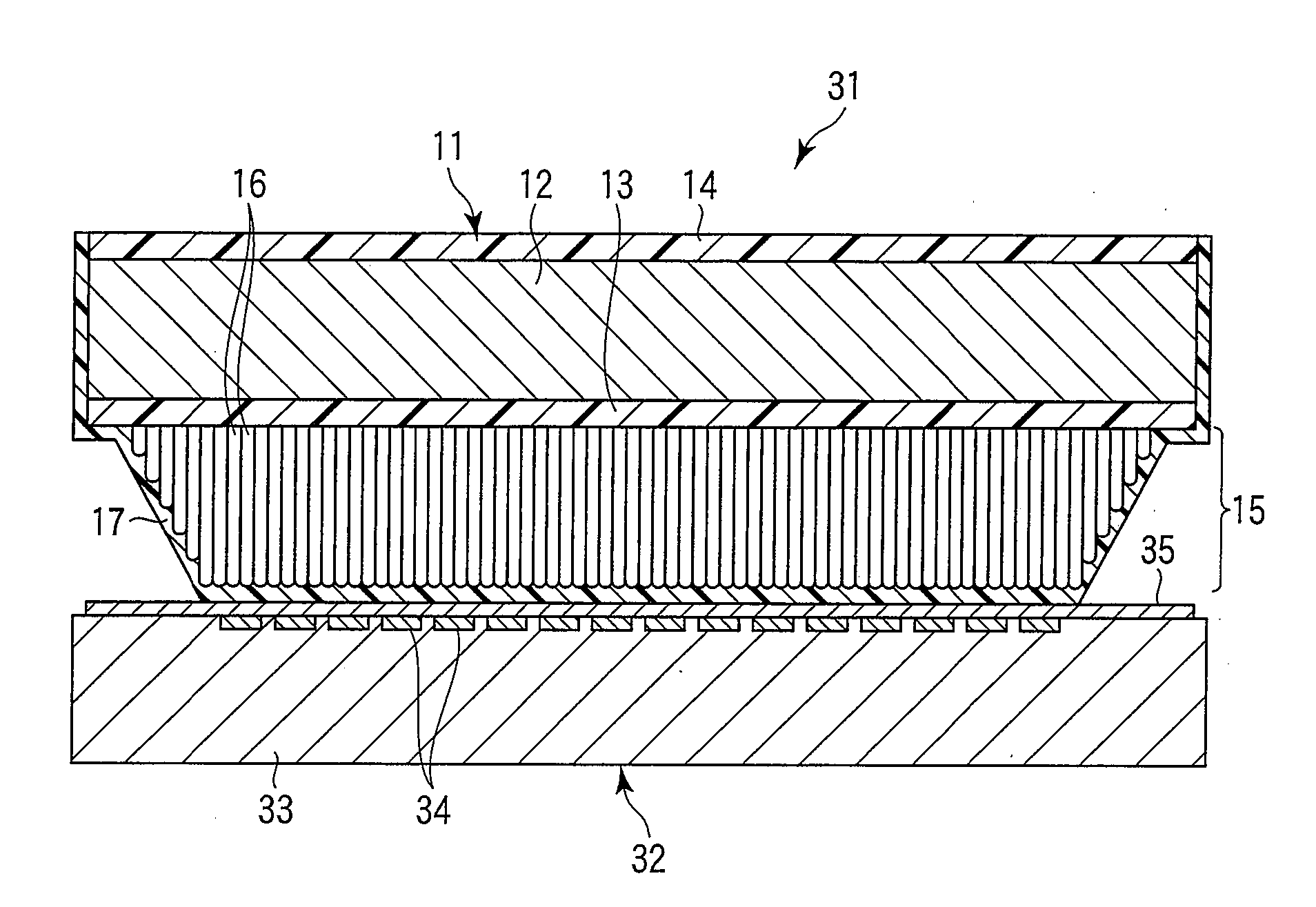
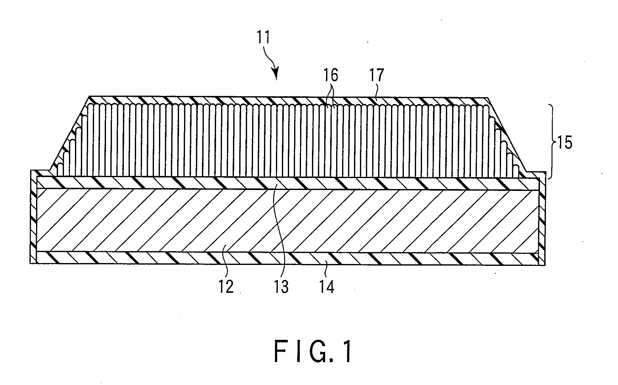
[0022]FIG. 1 is a cross-sectional view illustrating a scintillator panel 11 having a supporting substrate 12 of a carbon fiber-reinforced plastic (hereinafter, referred to as CFRP), a reflective resin sheet 13 of a polyethylene terephthalate foam having a thickness of 190 μm (expanded PET) as a reflective film formed on one entire surface of the supporting substrate 12, and a resin sheet 14 of a polyethylene terephthalate foam (expanded PET) having a thickness of 190 μm, which is the same as that of the reflective resin sheet 13, formed on the other entire surface of the supporting substrate 12.

[0023]The supporting substrate 12 is prepared by laminating multiple fiber-reinforced base materials, impregnating the composite plate with a thermosetting resin, and then, heat-curing the resulting composite plate.

[0024]The reflective resin sheet 13 and the resin sheet 14 may be formed ...


PUM


Abstract

A reflective resin sheet is bonded to one face of a supporting substrate transmitting a radiation ray and a resin sheet of the same material as that of the reflective resin sheet to the other face of the supporting substrate. A phosphor layer converting a radiation ray into visible light is formed additionally on the reflective resin sheet formed on one face of the supporting substrate. The phosphor layer is enclosed with an additional moisture-proof layer and the reflective resin sheet. It is possible to obtain a scintillator panel higher in sensitivity characteristics, stabilized in quality and more cost-effective by placing the reflective resin sheet between the supporting substrate and the phosphor layer.

Description

CROSS-REFERENCE TO RELATED APPLICATIONS[0001]This is a Continuation Application of PCT Application No. PCT / JP2008 / 055696, filed Mar. 26, 2008, which was published under PCT Article 21(2) in Japanese.[0002]This application is based upon and claims the benefit of priority from prior Japanese Patent Application No. 2007-080420, filed Mar. 27, 2007, the entire contents of which are incorporated herein by reference.BACKGROUND OF THE INVENTION[0003]1. Field of the Invention[0004]The present invention relates to a scintillator panel converting radiation rays to visible light and a radiation detector using the scintillator panel.[0005]2. Description of the Related Art[0006]Recent digitalized radiation detectors, such as those for medical tests or industrial nondestructive inspections, are mainly systems employing a method of converting incident X rays to visible light in a scintillator layer such as computed radiology (hereinafter, referred to as CR) and flat panel detectors (hereinafter, r...

Claims


Application Information

Patent Timeline
IPC IPC(8): G01J1/42G01J1/58
CPCC09K11/613C09K11/7733G21K2201/06G21K4/00G01T1/202G01T1/20H01L27/14H04N5/32
Inventor YOSHIDA, ATSUYAHORIUCHI, HIROSHI
Owner CANON ELECTRON TUBES & DEVICES CO LTD
Why Eureka
Try Eureka