Minimum loss and wiring circuit and method for paralleling hot swap controllers

a wiring circuit and controller technology, applied in the field of low loss and wiring circuit for paralleling hot swap controllers, can solve the problems of excessive power loss, high power dissipation loss, waste of power from ballast resistors, etc., and achieve equal load current sharing, reduce power dissipation, and reduce current hogging

Active Publication Date: 2010-01-14
TEXAS INSTR INC
View PDF30 Cites 21 Cited by
  • Summary
  • Abstract
  • Description
  • Claims
  • Application Information

AI Technical Summary

Benefits of technology

[0024]It is another object of the invention to provide a hot swap controller which can achieve approximately equal load current sharing and can also provides substantially reduced power dissipation compared to hot swap controllers of the prior art.
[0025]It is another object of the invention to provide a hot swap controller which can achieve approximately equal load curren

Problems solved by technology

The ballast resistor technique has been an effective way of providing relatively equal sharing of current from the two or more power-supplying elements, but suffers from the major disadvantage that a substantial amount of power is dissipated in the ballast resistors and therefore is wasted.
This circuit does not use ballast resistors but rather depends more on the diodes D2, which also suffer excessive power losses.
Unfortunately, the n+1 redundant power supply system 10 of Prior Art FIG. 2 has the shortcoming of high power dissipation loss which is unacceptable in state-of-the-art hot swap controller applications.
The paralleling circuitry is complex and not readily adaptable in any form to hot swap controllers.
It is very difficult in such an environment to connect multiple hot swap controllers in parallel such that they approximately equally share the total load current so as to avoid damage to edge connector pins of the circuit cards.
The resulting momentary decrease in the regulated supply voltage provided to the circuitry of the vario

Method used


Image

  • Minimum loss and wiring circuit and method for paralleling hot swap controllers
  • Minimum loss and wiring circuit and method for paralleling hot swap controllers
  • Minimum loss and wiring circuit and method for paralleling hot swap controllers

Examples


Embodiment Construction

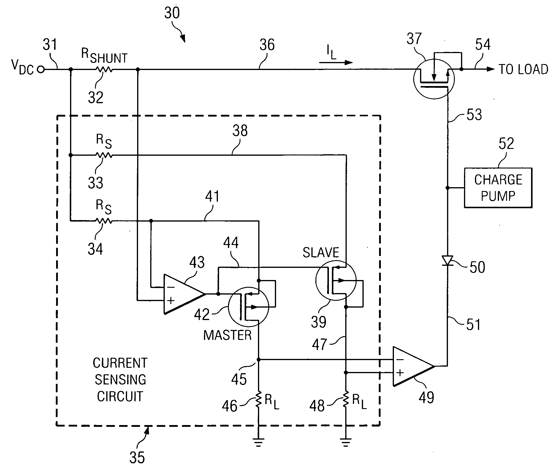
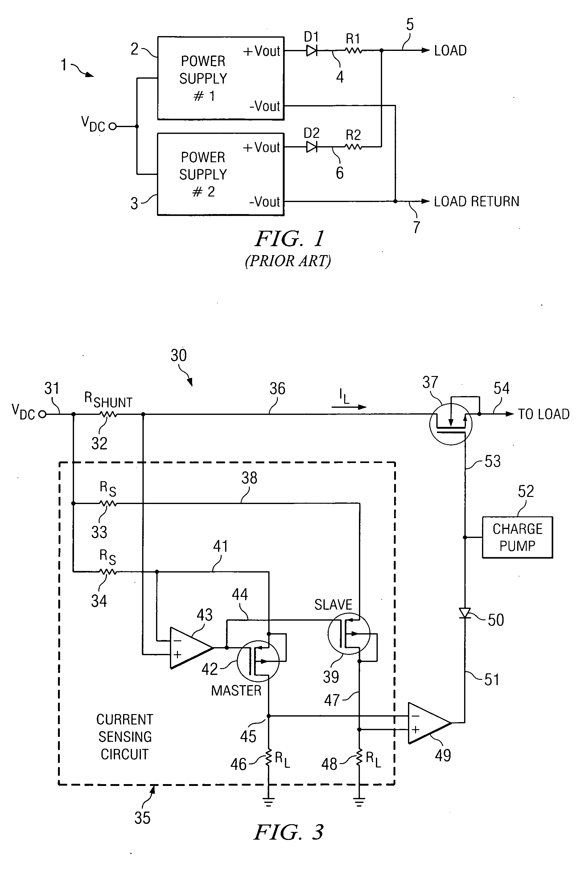
[0040]The invention provides a structurally simple hot swap controller and technique for achieving effective parallel connection of two (or more) of the hot swap controllers in such a way as to cause them to deliver equal amounts of current to a common load with a reduced amount of wasted power dissipation compared to prior parallel-coupled hot-swap controllers. The “weaker” of the parallel-connected hot swap controllers (i.e., the one having the highest “on” resistance in its output power transistor) operates with its output transistor in a fully-turned-on mode, and the “stronger” of the parallel-connected hot swap controllers operates to adjust itself in response to current in the output transistor of the weaker hot swap controller so the stronger hot swap controller contributes only an amount of the load current equal to the contribution by the weaker hot swap controller. In a described embodiment, worst-case conditions result in a source-drain voltage drop across an output trans...


PUM


Abstract

A hot swap controller includes a shunt resistor (32-1,2) and a power transistor (37-1,2) having a source coupled to a load maintains the first power transistor in a fully-turned-on condition to cause it to deliver a load current contribution (I1,2) which flows through the shunt resistor and the power transistor to the load (25). Current sensing circuitry (35-1,2) produces a first control signal (V45-1,2-V47-1,2) equal to the difference between a DC component (V47-1) proportional to a first load current contribution (IL1) flowing in the first shunt resistor and a feedback-based component (V45-1). A control amplifier (49-1,2) produces a second control signal (V51-1,2) in response to the first control signal to modify a drive signal (53-1) to the power transistor so as to reduce a channel resistance of the power transistor if the first control signal exceeds a predetermined level.

Description

BACKGROUND OF THE INVENTION[0001]The present invention relates generally to hot swap controllers which can be inserted into and / or removed from a power supply system, such as the power supply system of a server back plane, to connect or disconnect power to a particular load while power continues to be supplied to the load by means of other hot swap controllers which are already plugged into the power supply system. More particularly, the invention relates to a hot swap controller that is capable of providing minimum voltage loss, minimum power dissipation, and maximum power utilization efficiency.[0002]The closest prior art is believed to include the brochure “hp Carrier Grade Blade Server bh3710 Site Preparation Guide, Edition 2.0”, copyright 2002-2004 by Hewlett-Packard Development Company, L. P., the publication “Passive Current Sharing Boosts Power and Reliability” by Berry Ehrman, Power Electronics Technology, pages 58 and 56, January, 2005, and the published Application Note 1...

Claims


Application Information

Patent Timeline
IPC IPC(8): H01H35/00
CPCH02J1/102H02J1/001
Inventor STEELE, GERALD W.LARSON, TONY R.
Owner TEXAS INSTR INC
Why Eureka
Try Eureka