Safety drive for a flap or a valve

a safety drive and flap technology, applied in the field of safety drives, can solve the problems of switch and sensor use, spring loss, and increase the wear of mechanics, and achieve the effect of significantly simplifying the electric energy flux

Active Publication Date: 2010-01-14
BELIMO HOLDING AG
View PDF9 Cites 31 Cited by
  • Summary
  • Abstract
  • Description
  • Claims
  • Application Information

AI Technical Summary

Benefits of technology

[0030]The arrangement according to the invention allows the electric energy flux to be significantly simplified in both directions, in other words for charging and discharging the capacitive energy store, by v

Problems solved by technology

However, these spring systems which have been used for a long time always have the disadvantage that they give rise to increased wear of the mechanics and that the spring loses its tension over time.
It has a disadvantageous effect that a switch and a sensor have to be used for the voltage relay.
The emergency

Method used


Image

  • Safety drive for a flap or a valve
  • Safety drive for a flap or a valve
  • Safety drive for a flap or a valve

Examples


Embodiment Construction

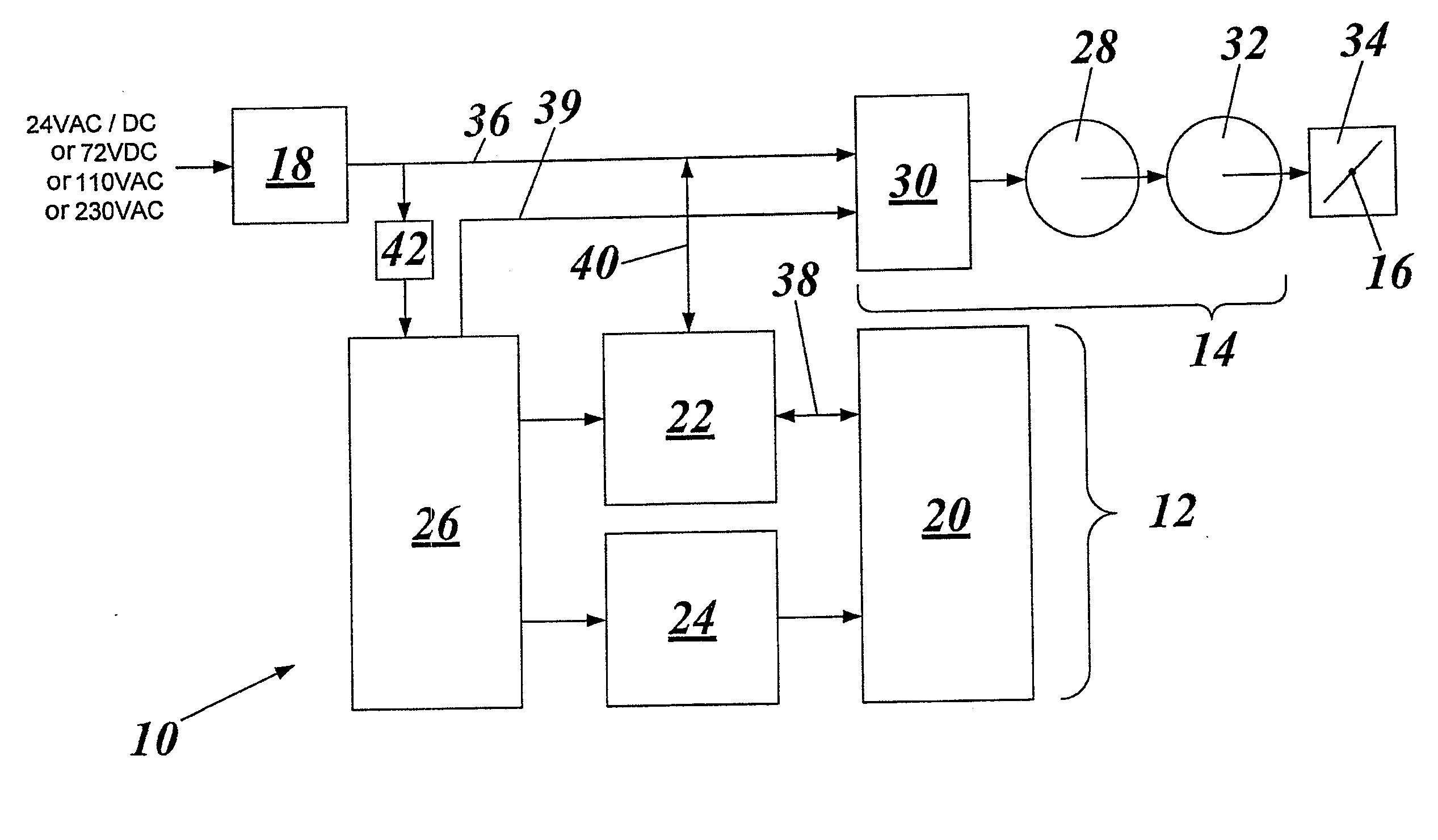
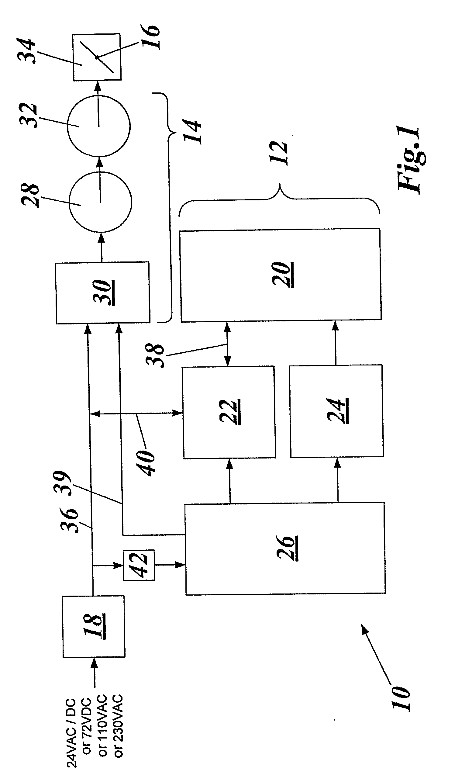
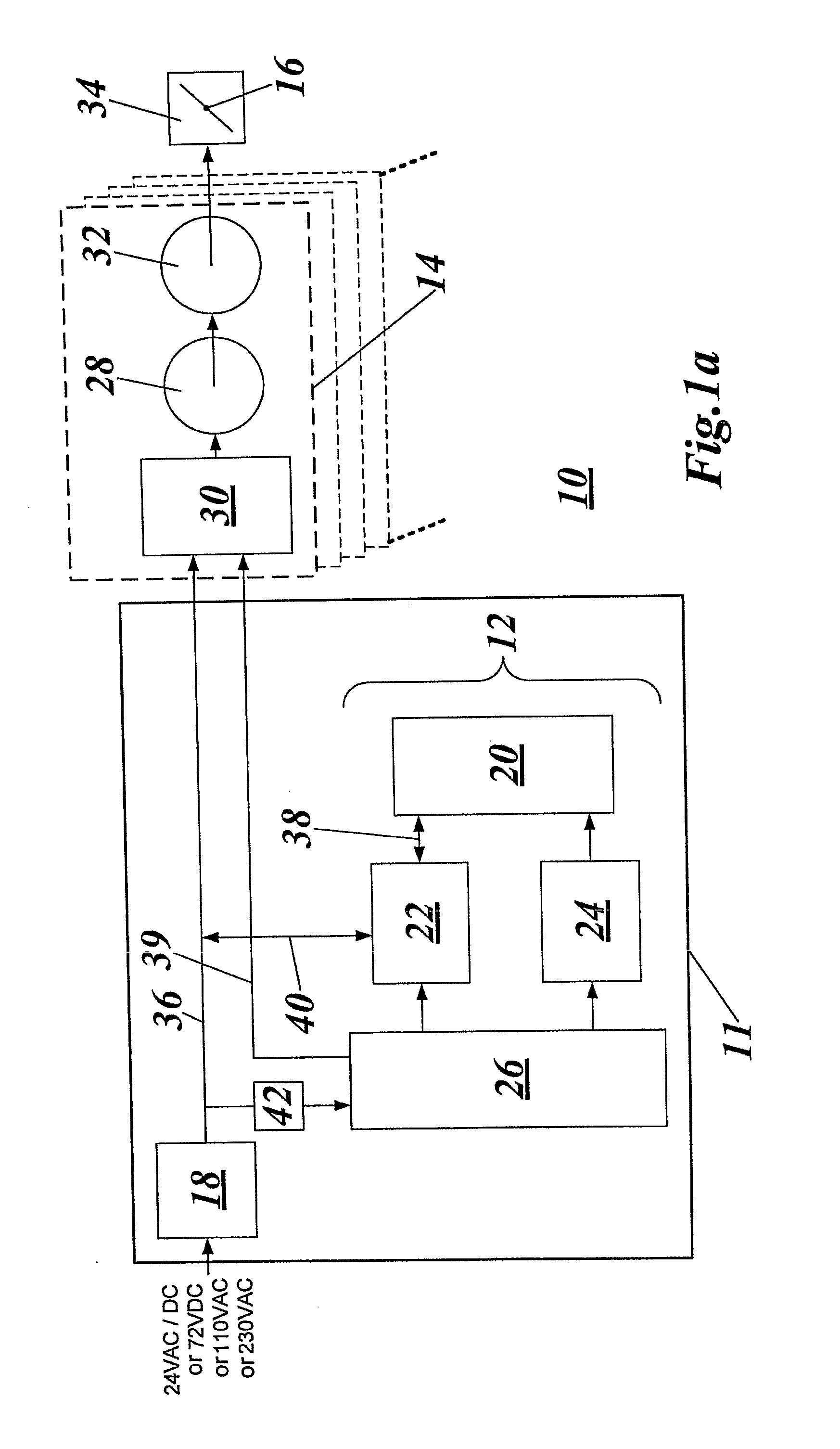
[0050]FIG. 1 shows a safety drive 10 with a safety circuit 12, an actuator drive 14 with electric motor 28 for a flap 16, and a power feed 18.

[0051]The safety circuit 12 comprises a capacitive energy store 20, generally one or more double layer capacitors, usually referred to as supercap for the sake of simplicity. An energy converter 22 has an energy flux (44 in FIG. 2) in two directions. It lowers the voltage in order to charge the supercap 20 and increases it to the original value, specifically to the normal voltage of the electric motor 28, when the supercap 20 is discharged. A balancing and monitoring unit 24 serves, on the one hand, to monitor the capacitor or the individual capacitors of the energy store 20, and on the other hand serves to balance the voltage between different capacitors of the energy store 20. The details relating to the energy converter 22 and the balancing and monitoring unit 24 follow in FIGS. 2-6. The safety circuit 12 is controlled and monitored by a co...


PUM


Abstract

A safety drive unit (10) with a safety circuit (12) resets a flap or a valve into a specified safety position for controlling a gas or liquid volumetric flow, in particular in the field of heating, ventilation, and air conditioning (HVAC) fire protection and monitoring systems. The safety drive unit (10) essentially comprises an actuator (14) with a controllable electric motor (28), a capacitive energy storage unit (20), an energy converter (22) with a power module, and a power supply (18). During normal operation, the electric current in the power module of the energy converter (22) is converted to a lower voltage and stored in the capacitive energy storage unit (20) with at least one double-layer capacitor. If the voltage drops below a predetermined value or if there is a power failure, the stored electrical charge is converted back to a higher voltage by the same power module, and the electric motor (28) is activated until the specified safety position is reached.

Description

TECHNICAL FIELD[0001]The invention relates to a safety drive having a safety circuit for a flap or a valve for controlling a gas volume flow or fluid volume flow, in particular in the field of heating / venting air conditioning (HLK), fire protection and room protection, into a predefined safety position. Furthermore, the invention relates to a method for the assured return of the flap or the valve into the aforementioned safety position. The safety circuit becomes active if a voltage failure or voltage drop is detected.PRIOR ART[0002]In order to move a flap in a ventilating system or a valve in a water conducting system, relatively weak motors have to activate control elements which have large areas or large volumes. Precise and stable adjustment is possible with a pronounced step-down ratio. In order to pivot a flap or rotate a ball valve through an acute, right-angled or oblique angle, numerous rotations of the drive shaft of the electric motor are necessary. If a valve is displace...

Claims


Application Information

Patent Timeline
IPC IPC(8): G05B9/02H02J9/06H02P27/00
CPCH02J9/062H02J7/0016F24F2013/1433
Inventor OCHSENBEIN, MARTINSTAHELI, CURDINFURRER, ROMAN
Owner BELIMO HOLDING AG
Why Eureka
Try Eureka