Dipole tag antenna structure mountable on metallic objects using artificial magnetic conductor for wireless identification and wireless identification system using the dipole tag antenna structure

a dipole tag and antenna technology, applied in the direction of resonant antennas, mechanical equipment, instruments, etc., can solve the problems of complex formation of amcs, ineffective operation of antennas, and inability of tag antennas mounted on conductors to operate as antennas, so as to facilitate the formation of wireless identification systems, easy manufacturing, and easy mounting

Inactive Publication Date: 2010-01-14
ELECTRONICS & TELECOMM RES INST
View PDF11 Cites 284 Cited by
  • Summary
  • Abstract
  • Description
  • Claims
  • Application Information

AI Technical Summary

Benefits of technology

[0022]A dipole tag antenna structure using an AMC according to the present invention includes a chip for identifying wireless signal information and for supplying power. Also, the dipole tag antenna structure according to the present invention does not require a feeding port. The dipole tag antenna structure can be mounted directly on a conductor. In addition, the dipole tag antenna structure can be formed in a low-profile structure to be directly mounted on the conductor.
[0023]Moreover, the AMC can be formed so as not to include vias and thus can be easily manufactured. Also, patterns of an AMC layer and the dipole tag antenna can be formed in various shapes. In particular, the dipole tag antenna can be realized in a structure having the shape of ‘{tilde over ( )},’ and design parameters can be appropriately changed to appropriately adjust a frequency band and an identification distance of the dipole tag antenna.
[0024]Furthermore, the dipole tag antenna structure can be mounted directly on the conductor and thus easily mounted on various products including vehicles, containers, etc. so as to easily realize a wireless identification system. Consumers can be provided with various options with the expansion of applications of the wireless identification system.

Problems solved by technology

As a result, the antenna cannot operate effectively.
General tag antennas that are mounted on conductors cannot operate as antennas.
Accordingly, since a conventional antenna necessarily includes vias, the formation of an AMC is complicated.
Also, since a conventional antenna includes a feeding port for supplying power, a structure of the conventional antenna is complicated, and the size of the conventional antenna is increased.

Method used


Image

  • Dipole tag antenna structure mountable on metallic objects using artificial magnetic conductor for wireless identification and wireless identification system using the dipole tag antenna structure
  • Dipole tag antenna structure mountable on metallic objects using artificial magnetic conductor for wireless identification and wireless identification system using the dipole tag antenna structure
  • Dipole tag antenna structure mountable on metallic objects using artificial magnetic conductor for wireless identification and wireless identification system using the dipole tag antenna structure

Examples


Embodiment Construction

INDUSTRIAL APPLICABILITY

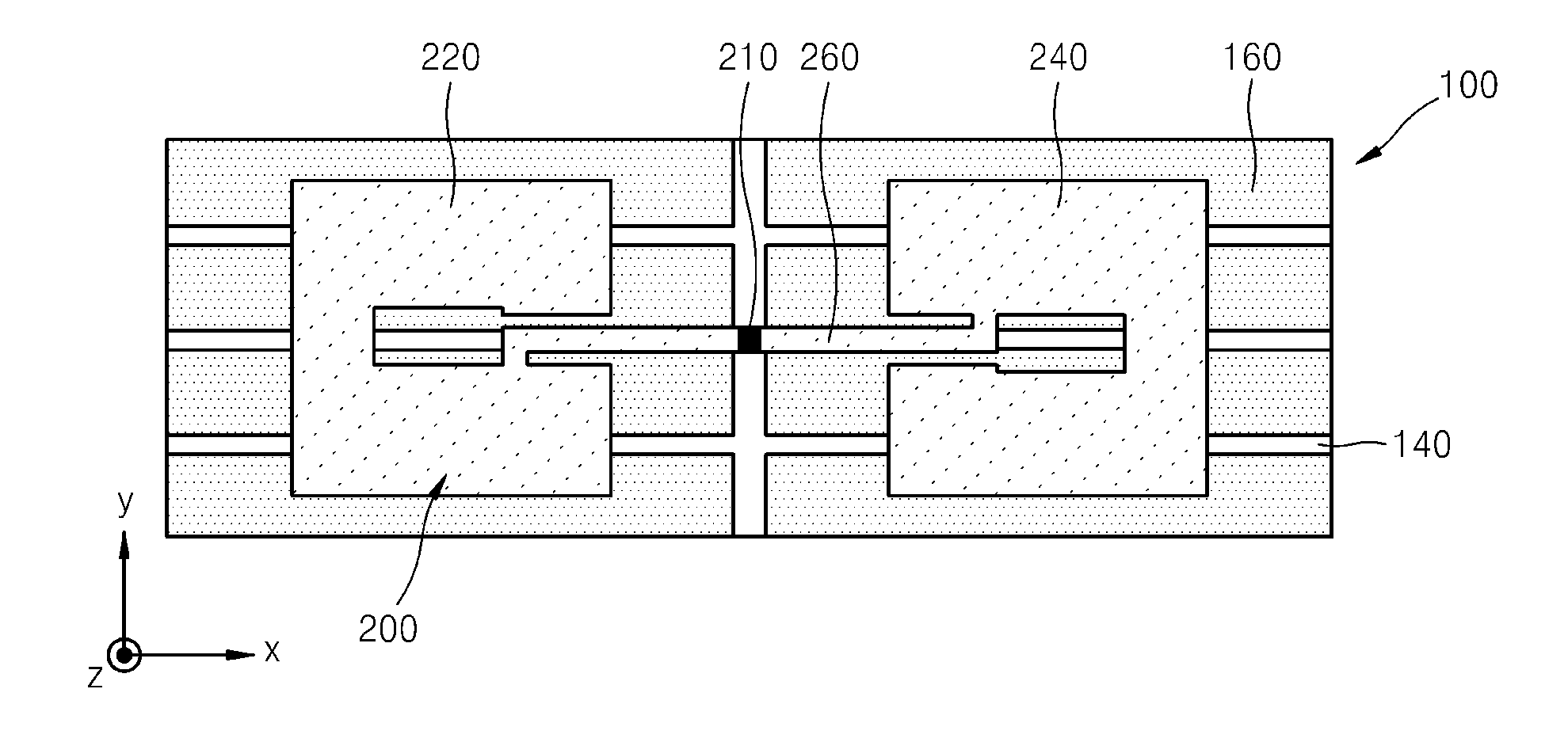
[0066]The present invention relates to an antenna and a wireless identification system using the antenna, and more particularly, to a dipole tag antenna using an artificial magnetic conductor (AMC) and a wireless identification system using the dipole tag antenna. The dipole tag antenna structure using an AMC according to the present invention includes a chip for identifying wireless signal information and for supplying power. Also, the dipole tag antenna structure according to the present invention does not require a feeding port. The dipole tag antenna structure can be mounted directly on a conductor. In addition, the dipole tag antenna structure can be formed in a low-profile structure to be directly mounted on the conductor.


PUM


Abstract

Provided are a dipole tag antenna using an artificial magnetic conductor (AMC) for wireless identification and a wireless identification system using the dipole tag antenna. The dipole tag antenna includes: a substrate formed of a first dielectric material; a conductive ground layer formed underneath the substrate; an AMC layer formed on the substrate; the dipole tag antenna mounted on the AMC layer and comprising a wireless identification chip; and the AMC directly mounted on a conductor.

Description

TECHNICAL FIELD[0001]This work was supported by the IT R&D program of MIC / IITA. [2005-S-047-02, Development of Material and Devices for EMI Suppression][0002]The present invention relates to an antenna and a wireless identification system using the antenna, and more particularly, to a dipole tag antenna using an artificial magnetic conductor (AMC) and a wireless identification system using the dipole tag antenna.BACKGROUND ART[0003]A magnetic conductor corresponds to a general electric conductor. A tangential component of an electric field is almost ‘0’ on a surface of an electric conductor, while a tangential component of a magnetic field is almost ‘0’ on a surface of a magnetic conductor. Thus, a current does not flow on the surface of a magnetic conductor differently from that of an electric conductor.[0004]A magnetic conductor operates as a component which has a considerably high resistance in a specific frequency, i.e., performs a function of an open circuit, due to the charact...

Claims


Application Information

Patent Timeline
Patent Type & Authority Applications(United States)
IPC IPC(8): H01Q9/16G06K19/06
CPCH01Q1/2225H01Q15/008H01Q9/285F16H55/14F16H55/17
Inventor SIM, DONG-UKCHOI, HYUNG-DOKWON, JONG-HWAKIM, DONG-HOCHOI, JAE-ICK
Owner ELECTRONICS & TELECOMM RES INST
Why Eureka
Try Eureka