Liquid ejecting head, liquid ejecting apparatus, and piezoelectric element

a liquid ejecting and liquid ejecting technology, applied in the direction of piezoelectric/electrostrictive/magnetostrictive devices, device material selection, piezoelectric/electrostrictive device material selection, etc., can solve the problems of difficult stab and continuous sputtering of an oxide, deformation disadvantageous breakage of the piezoelectric layer, so as to reduce the stress of the diffusion-preventing layer

Active Publication Date: 2010-01-14
SEIKO EPSON CORP
View PDF0 Cites 2 Cited by
  • Summary
  • Abstract
  • Description
  • Claims
  • Application Information

AI Technical Summary

Benefits of technology

[0011]An advantage of some aspects of the invention is to provide a liquid ejecting head having a piezoelectric element that prevents a piezoelectric layer from being broken and that has improved durability, a liquid ejecting apparatus, and a piezoelectric element.
[0013]According to the aspect described above, even when iridium is oxidized to form the diffusion-preventing layer, the stress of volume expansion caused by oxidation can be relieved by the stress relieving holes. As a result, the stress of the diffusion-preventing layer applied to other laminate films is decreased, so that delamination, breakage of the piezoelectric layer, degradation in durability, and the like can be prevented.
[0014]It is preferable that the diffusion-preventing layer of the first electrode be provided at a piezoelectric layer side, and that the above liquid ejecting head further include a crystalline seed layer containing titanium oxide as a primary component between the diffusion-preventing layer and the piezoelectric layer. In addition, the first electrode preferably has a titanium oxide region that contains titanium oxide as a primary component and that is in contact with the crystalline seed layer through the stress relieving holes. As a result, excess titanium of the piezoelectric layer at a first electrode side can be easily discharged to a titanium oxide region side, and the piezoelectric layer can be formed to have uniform piezoelectric properties in the thickness direction thereof.
[0015]In addition, the first electrode preferably further has a platinum layer containing platinum as a primary component. Accordingly, the conductivity of the first electrode is not degraded even when the piezoelectric layer is fired, so that the conductivity of the first electrode can be ensured.
[0017]Furthermore, according to another aspect of the invention, there is provided a liquid ejecting apparatus including the liquid ejecting head described above. According to this aspect, a liquid ejecting apparatus including a liquid ejecting head excellent in liquid injection properties and durability can be realized.
[0019]According to the aspect described above, even when iridium is oxidized to form the diffusion-preventing layer, the stress of volume expansion caused by oxidation can be decreased by the stress relieving holes. As a result, the stress of the diffusion-preventing layer applied to other laminate films is decreased, so that delamination, breakage of the piezoelectric layer, degradation in durability, and the like can be prevented.

Problems solved by technology

As a result, the durability of the piezoelectric layer is degraded, and breakage thereof may disadvantageously occur.
In addition, although an iridium oxide film may be directly formed by sputtering, it is difficult to stably and continuously perform sputtering of an oxide.
As a result, an oxide having desired thickness, density, and the like cannot be obtained, and the cost is also unfavorably increased.
In addition, the problems described above are not limited to a piezoelectric element used for an ink jet recording head, and piezoelectric elements used for liquid ejecting heads ejecting other types of liquids and piezoelectric elements used for devices other than liquid ejecting heads also have the above problems.

Method used


Image

  • Liquid ejecting head, liquid ejecting apparatus, and piezoelectric element
  • Liquid ejecting head, liquid ejecting apparatus, and piezoelectric element
  • Liquid ejecting head, liquid ejecting apparatus, and piezoelectric element

Examples


embodiment 1

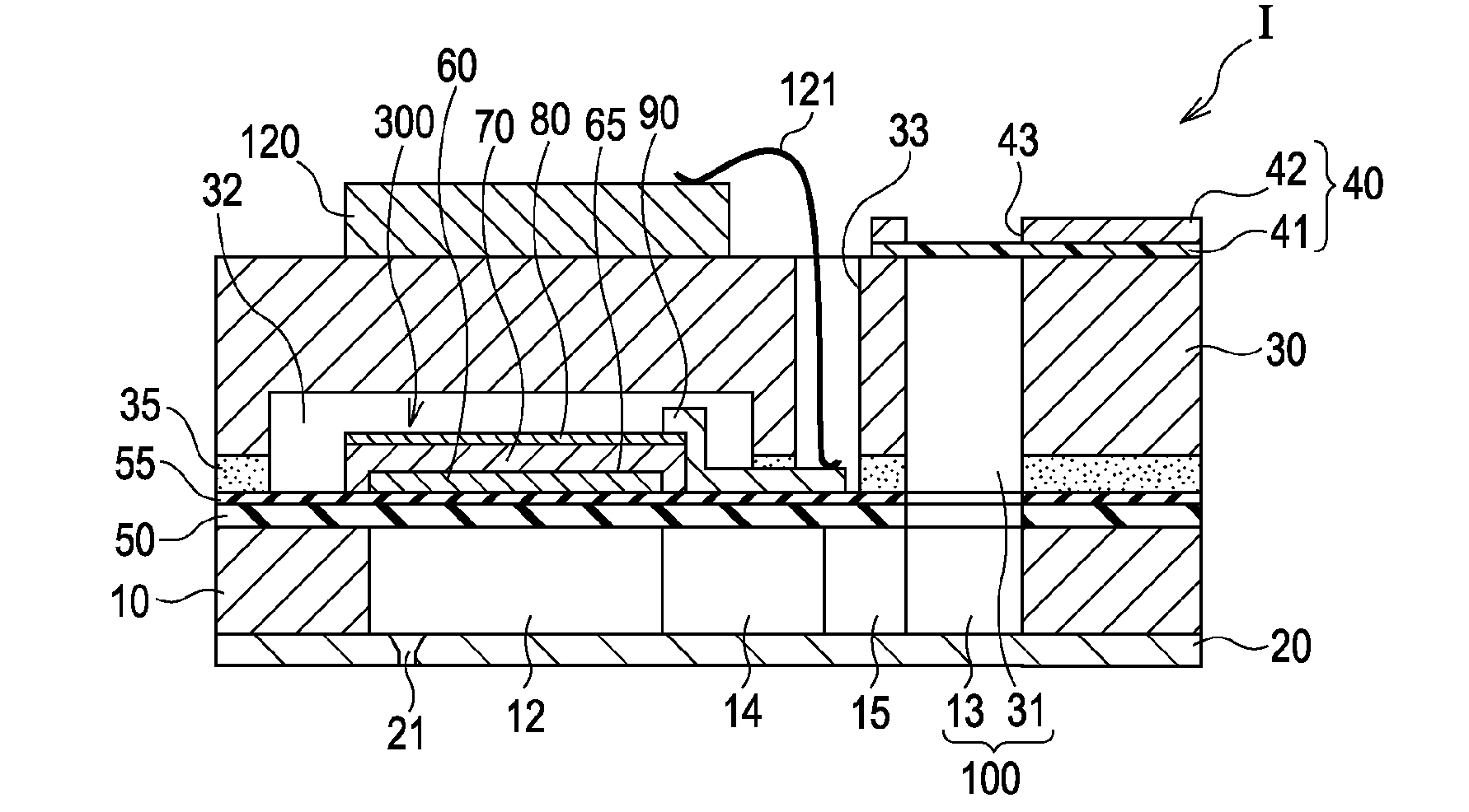
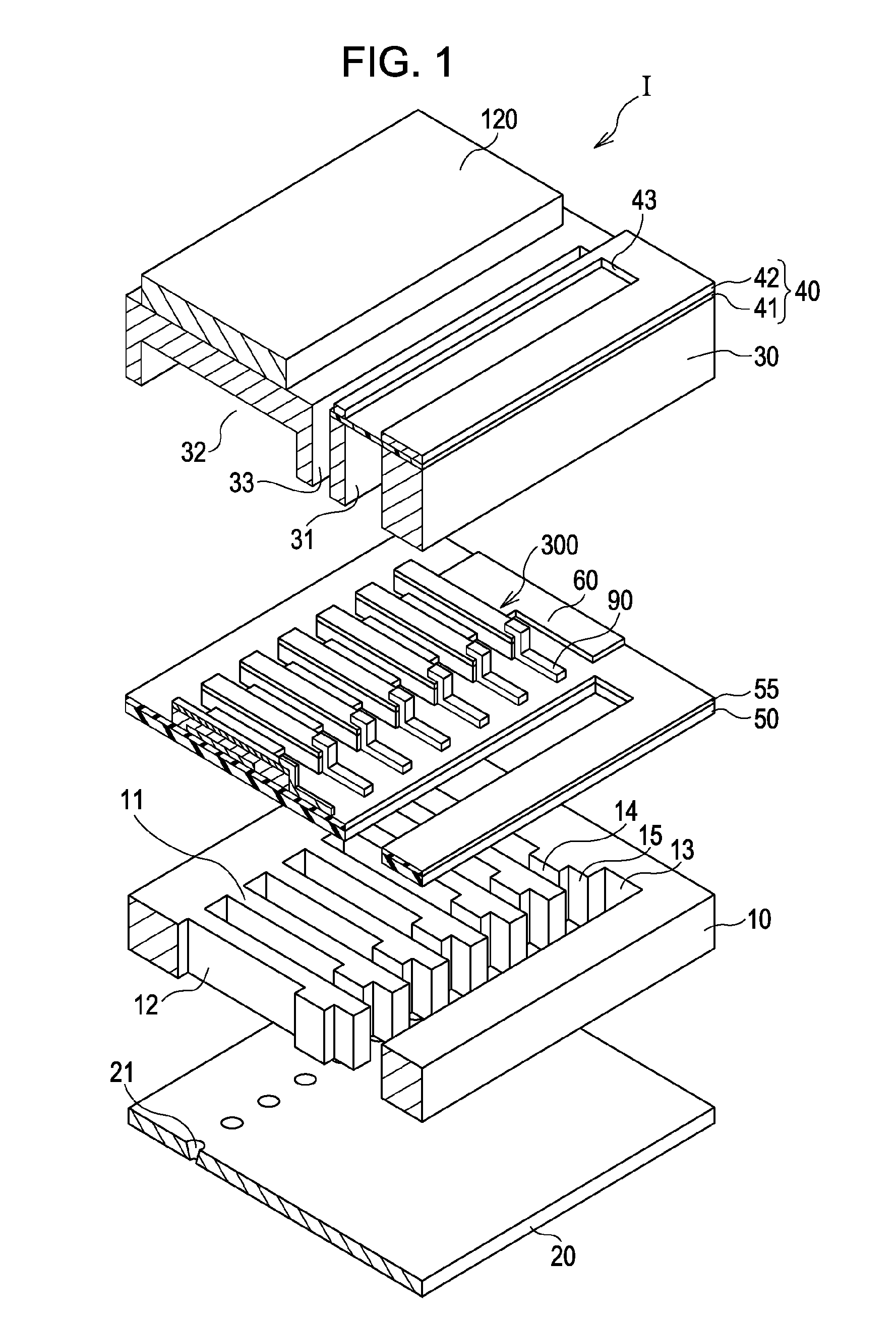
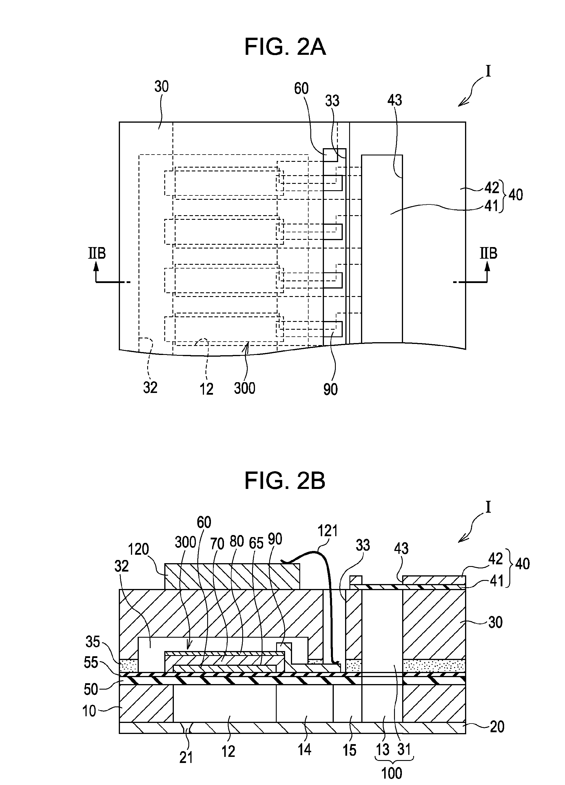
[0033]FIG. 1 is an exploded perspective view showing a schematic structure of an ink jet recording head I which is one example of a liquid ejecting head according to Embodiment 1 of the invention; FIG. 2A is a plan view of FIG. 1; FIG. 2B is a cross-sectional view taken along the line IIB-IIB of FIG. 2A; and FIG. 3 is an enlarged cross-sectional view showing an important portion of the ink jet recording head I.

[0034]As shown in FIGS. 1, 2A, and 2B, a flow path forming substrate 10 of this embodiment is composed of a silicon single crystal substrate, and an elastic film 50 composed of silicon dioxide is formed on one surface of the substrate 10.

[0035]In the flow path forming substrate 10, pressure generating chambers 12 are provided in parallel in the width direction thereof. In addition, a communicating portion 13 is formed in an outside region in the longitudinal direction of the pressure generating chambers 12 of the flow path forming substrate 10 to communicate with the pressure ...


PUM


Abstract

A liquid ejecting head includes a pressure generating chamber communicating with a nozzle opening, and a piezoelectric element generating a pressure change in the pressure generating chamber. In this liquid ejecting head, the piezoelectric element includes a first electrode, a piezoelectric layer provided above the first electrode, and a second electrode provided above the piezoelectric layer at a side opposite to the first electrode. The first electrode has a diffusion-preventing layer containing iridium oxide as a primary component, and the diffusion-preventing layer has stress relieving holes that pass through in the thickness direction thereof and that is filled with a material other than iridium oxide.

Description

CROSS-REFERENCE TO RELATED APPLICATIONS[0001]This application claims the benefit of priority to Japanese Patent Application No. 2008-182384 filed Jul. 14, 2008, the contents of which are hereby incorporated by reference in their entirety.BACKGROUND[0002]1. Technical Field[0003]The present invention relates to a liquid ejecting head ejecting a liquid from a nozzle opening, a liquid ejecting apparatus, and a piezoelectric element having a first electrode, a piezoelectric layer, and a second electrode.[0004]2. Related Art[0005]A piezoelectric element used for a liquid ejecting head or the like is an element including two electrodes and a dielectric film provided therebetween, the dielectric film including a piezoelectric material that has an electromechanical transducing function, and the dielectric film is formed, for example, of a crystallized piezoelectric ceramic.[0006]The piezoelectric element as described above is formed by the steps of forming a lower electrode film on one surfa...

Claims


Application Information

Patent Timeline
Patent Type & Authority Applications(United States)
IPC IPC(8): B41J2/045B41J2/055B41J2/135B41J2/14B41J2/145B41J2/16H01L41/09H01L41/18H01L41/187H01L41/22H01L41/29H01L41/319
CPCB41J2202/03B41J2/14233
Inventor MOROZUMI, KOICHIKATO, JIRODENDA, SATOSHIASAOKA, ICHIRO
Owner SEIKO EPSON CORP
Why Eureka
Try Eureka