Supercharge Your Innovation With Domain-Expert AI Agents!

Method and System for Localization Using One-Way Ranging Technique

a one-way ranging and localization technology, applied in the field of one-way ranging methods and systems, can solve the problems of increasing power consumption and calculation load, difficult to use in a room or a shadowed area, and low accuracy of global positioning tracking technology using gps or mobile communication networks, so as to reduce power consumption and reduce size, the effect of removing the inaccuracy of distance ranging

Inactive Publication Date: 2010-01-14
GWANGJU INST OF SCI & TECH
View PDF9 Cites 29 Cited by
  • Summary
  • Abstract
  • Description
  • Claims
  • Application Information

AI Technical Summary

Benefits of technology

The present invention provides a method and system for determining the position of a target node in a wireless network using a one-way ranging technique. The method involves calculating the time difference between signals transmitted from the target node and the reference node, and from the target node and the first fixed node. This allows for the position of the target node to be determined based on the time difference and the known positions of the reference node and the fixed nodes. The invention has several technical effects, including reducing power consumption, achieving low latency, and removing inaccuracy due to clock drift and response time differences.

Problems solved by technology

In the business, one of the technical core problems is to track a position of a mobile tag attached to a pedestrian, a mobile object, a fixed target, etc., with desired precision.
However, there are problems in that a global position tracking technology using the GPS or the mobile communication network has low position determination accuracy as well as being difficult to use in a room or a shadowed area.
However, the SDS-TWR technology has the following problems.
Since the SDS-TWR uses the round-trip time, the receiver and the transmitter each should have both the transmitting function and receiving function, which increases power consumption and calculation load.
In addition, the response time in the transmitter and the receiver is previously set as described above, which causes a problem in that it is impossible to reflect variable environment conditions.
Further, as described above, the clock drift and the crystal offset of the oscillator serve as fundamental causes of a distance ranging error of the SDS-TWR.
Moreover, there is a problem due to the movement of the node whose position should be determined.
The longer the distance ranging delay, the more the distance ranging error is increased.

Method used


Image

  • Method and System for Localization Using One-Way Ranging Technique
  • Method and System for Localization Using One-Way Ranging Technique
  • Method and System for Localization Using One-Way Ranging Technique

Examples


Embodiment Construction

[0028]Hereinafter, preferred embodiments of the present invention will be described in detail with reference to the accompanying drawings. First of all, it is to be noted that in giving reference numerals to elements of each drawing, like reference numerals refer to like elements even though like elements are shown in different drawings. Further, in describing the present invention, well-known functions or constructions will not be described in detail since they may unnecessarily obscure the understanding of the present invention. Hereinafter, the preferred embodiment of the present invention will be described, but it will be understood to those skilled in the art that the spirit and scope of the present invention are not limited thereto and various modifications and changes can be made.

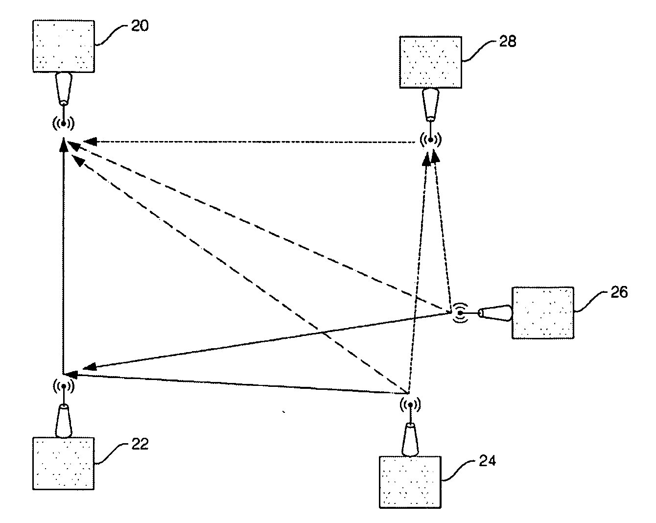
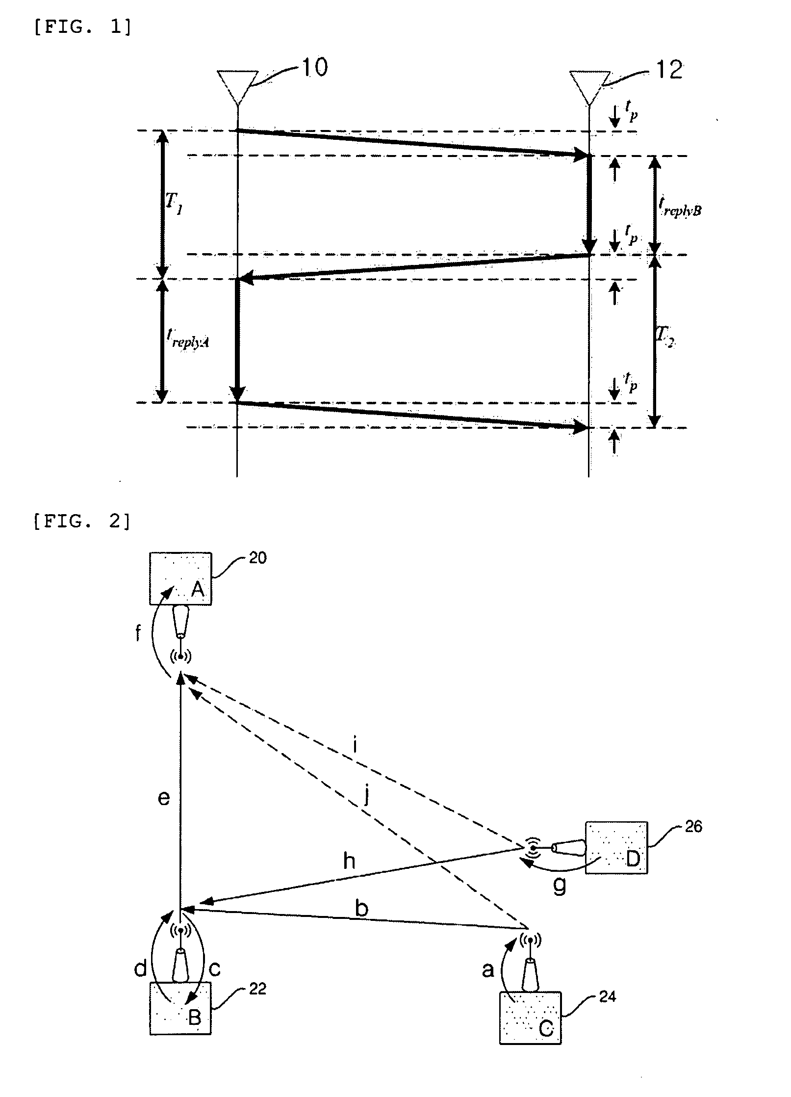
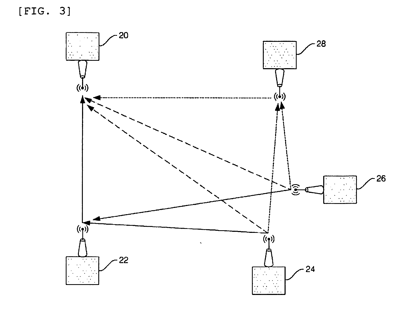
[0029]A system for determining a position according to the present invention determinates a position of a target node whose position should be determined using a one-way ranging technique.

[0030]Herei...


PUM


Abstract

The present invention relates to a method and system for determining a position using a one-way ranging technique. The present invention provides a method for determining a position of a target node in a wireless network, including a basic node, a first fixed node, a reference node, a target node, including: (a) calculating a time needed to directly transmit an RF signal originated from the reference node to the basic node and a time needed to arrive at the basic node via the first fixed node; (b) calculating a time needed to directly transmit the RF signal originated from the target node to the basic node and a time needed to arrive at the basic node via the first fixed node; and (c) determining the position of the target node based on the time calculated from steps (a) and (b).

Description

BACKGROUND OF THE INVENTION[0001]1. Field of the Invention[0002]The present invention relates to a method and system for determining a position using a one-way ranging technique. More specifically, the present invention relates to a method and system for determining a position using a one-way ranging technique that measures a position of a target node using the one-way ranging technique by using only the time difference of arrival between signals originated from the target node whose position should be determined and the time difference of arrival between signals originated from a reference node and determinates the position of the target node based on the measured position of the target node.[0003]2. Description of the Related Art[0004]It can be understood that a wireless sensor network (WSN) means a wireless network system having distributed sensing capability and an infrastructure. It has been demonstrated that the WSN technology is useful for a ubiquitous robot application field...

Claims


Application Information

Patent Timeline
Patent Type & Authority Applications(United States)
IPC IPC(8): H04B7/00
CPCG01S11/02G01S5/0289
Inventor AHN, HYO-SUNGHUR, HWAN
Owner GWANGJU INST OF SCI & TECH
Features
  • R&D
  • Intellectual Property
  • Life Sciences
  • Materials
  • Tech Scout
  • Unparalleled Data Quality
  • Higher Quality Content
  • 60% Fewer Hallucinations
Learn More