High Density Wave Channel Optical Data Communications

Inactive Publication Date: 2010-01-14
STANDARD SCI TECH
View PDF16 Cites 9 Cited by
  • Summary
  • Abstract
  • Description
  • Claims
  • Application Information

AI Technical Summary

Benefits of technology

[0013]Briefly and in general terms, the invention is directed to a system and associated method for communicating high density or large volumes of data optically. Large amounts of dat

Problems solved by technology

Prior to the use of optical information communication, most long-haul telecommunication and other “wired” communication networks were generally handled via electrical domain transmission, such as provided through wire cables, which is bandwidth limited.
Since the wavelength stabilization must be carried out for each semiconductor laser, the area of the apparatus occupied by the wavelength stabilizing circuit and the complexity of circuitry increase consistently with the number of lasers added and the wavelength multiplexing operations required.
This problem increases in severity as more channels are added in an attempt to increase the density of the data flow due to the increase in the number of lasers used and can become a significant problem for reliability and accuracy as well as substantially increasing costs.
As discussed above, in such a WDM transmission system increasing the number of wavelengths in order to increase the communication capacity of the system is met not only with stability problems of the semi-conductor lasers used for each channel but also with limitations such as the light amplification band limitation, the transmission band of the optical fiber limitation, bandwidth limitations of optical devices, and others.
In this approach, the precision of the semi-conductor laser light source for the each wavelength becomes an even greater issue as a factor to prevent an increase in the

Method used


Image

  • High Density Wave Channel Optical Data Communications
  • High Density Wave Channel Optical Data Communications
  • High Density Wave Channel Optical Data Communications

Examples


Example

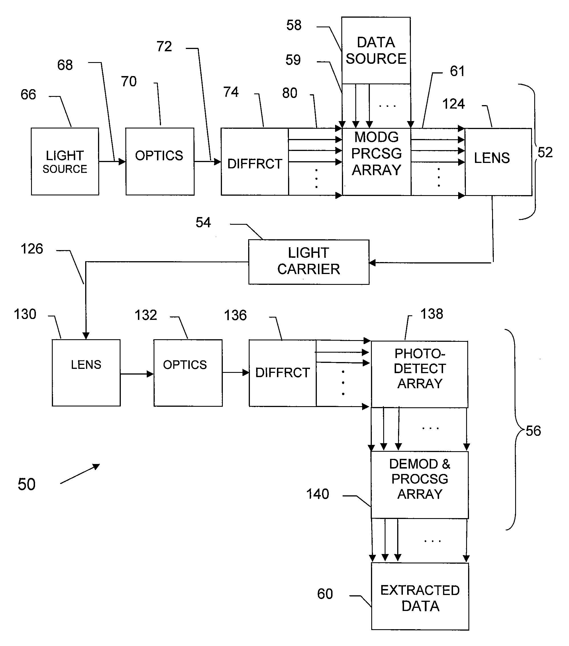
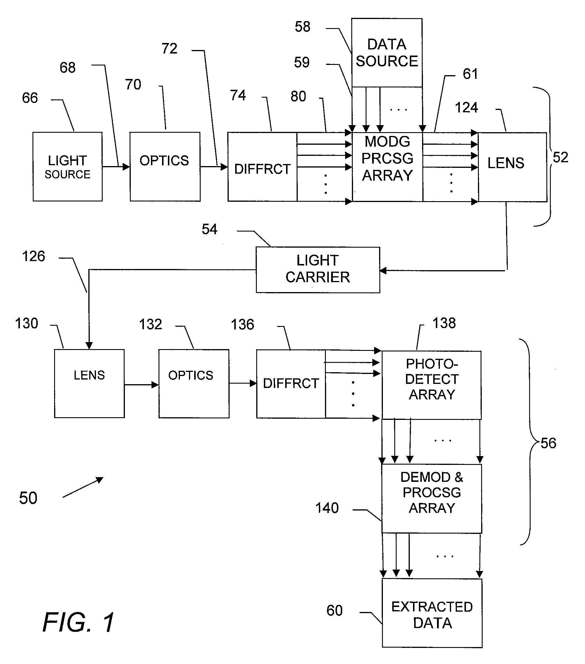
[0037]Referring now in more detail to the exemplary drawings for purposes of illustrating embodiments of the invention, wherein like reference numerals designate corresponding or like elements among the several views, there is shown in FIG. 1 an overall system block diagram and flow chart of a high density optical data communication system 50 in accordance with aspects of the invention. The embodiment shown includes a transmitter 52, a light carrier 54, and a receiver 56. In overview, a data source 58 provides data for communication to the receiver 56. The optical data communication system in accordance with the invention provides a system and method for communicating large amounts of that data in parallel optically.

[0038]As used herein, “data” is meant in its broad sense. That is the term “data” is meant to encompass signals, carrier waves or carrier signals, information, digital signals, analog signals, and other information in electrical or optical or other forms.

[0039]While in F...


PUM


Abstract

A high density data communications system and associated method comprises a multi-wavelength light source that provides a combined plurality of constituent lights having different wavelengths to a diffraction device that spatially separates the constituent lights to form a predetermined pattern of lights in order by their wavelengths, a light modulating processing array that individually modulates the separated lights in parallel according to data to form constituent light channels, a combiner that recombines the modulated separated light channels in parallel into a composite data communication light, a second diffraction device that spatially separates the modulated light channels into the predetermined pattern of wavelengths, and a demodulating processing array that extracts the data from the constituent modulated light channels.

Description

CROSS-REFERENCES TO RELATED APPLICATIONS[0001]This application claims priority from U.S. Provisional Application No. 61 / 079,050, filed Jul. 8, 2008, and incorporated herein by reference in its entirety.BACKGROUND[0002]The present invention relates to the optical communication of data and more particularly, to a system and associated method of providing a high density of individual optical wavelength channels for use in communicating data and signals.[0003]The landscape of optical data communication systems, networks, and methods has changed significantly over the past years. Prior to the use of optical information communication, most long-haul telecommunication and other “wired” communication networks were generally handled via electrical domain transmission, such as provided through wire cables, which is bandwidth limited. Telecommunication service providers in particular have in more recent years commercially deployed optical transport networks having vastly higher information or ...

Claims


Application Information

Patent Timeline
IPC IPC(8): H04J14/02
CPCG02F1/01G02F2201/305H04B10/548H04B10/506G02F2203/12
Inventor PRATT, RAYMOND ORSON
Owner STANDARD SCI TECH
Why Eureka
Try Eureka