Phase Shift Keyed Modulation of Optical Signal Using Chirp Managed Laser

Active Publication Date: 2010-01-14
II VI DELAWARE INC
View PDF0 Cites 49 Cited by
  • Summary
  • Abstract
  • Description
  • Claims
  • Application Information

AI Technical Summary

Benefits of technology

[0026]Although the precision of the analog-to-digital converters should be increased due to a more congested IQ constellation graph associated with 8PSK or 16PSK modulation as compared to QPSK modulation, the sampling rate may be significantly reduced, thereby reducing the complexity in implementing the analog-to-digital converters, especially in a dual polarization system in which the PSK modulated optical signal bit rate is 100 Gigabits per second or above. Furthermore, the electrical commu

Problems solved by technology

However, since 100 Gigabits per second is simply too fast for present Complementary Metal Oxide Semiconductor (CMOS) e

Method used


Image

  • Phase Shift Keyed Modulation of Optical Signal Using Chirp Managed Laser
  • Phase Shift Keyed Modulation of Optical Signal Using Chirp Managed Laser
  • Phase Shift Keyed Modulation of Optical Signal Using Chirp Managed Laser

Examples


Embodiment Construction

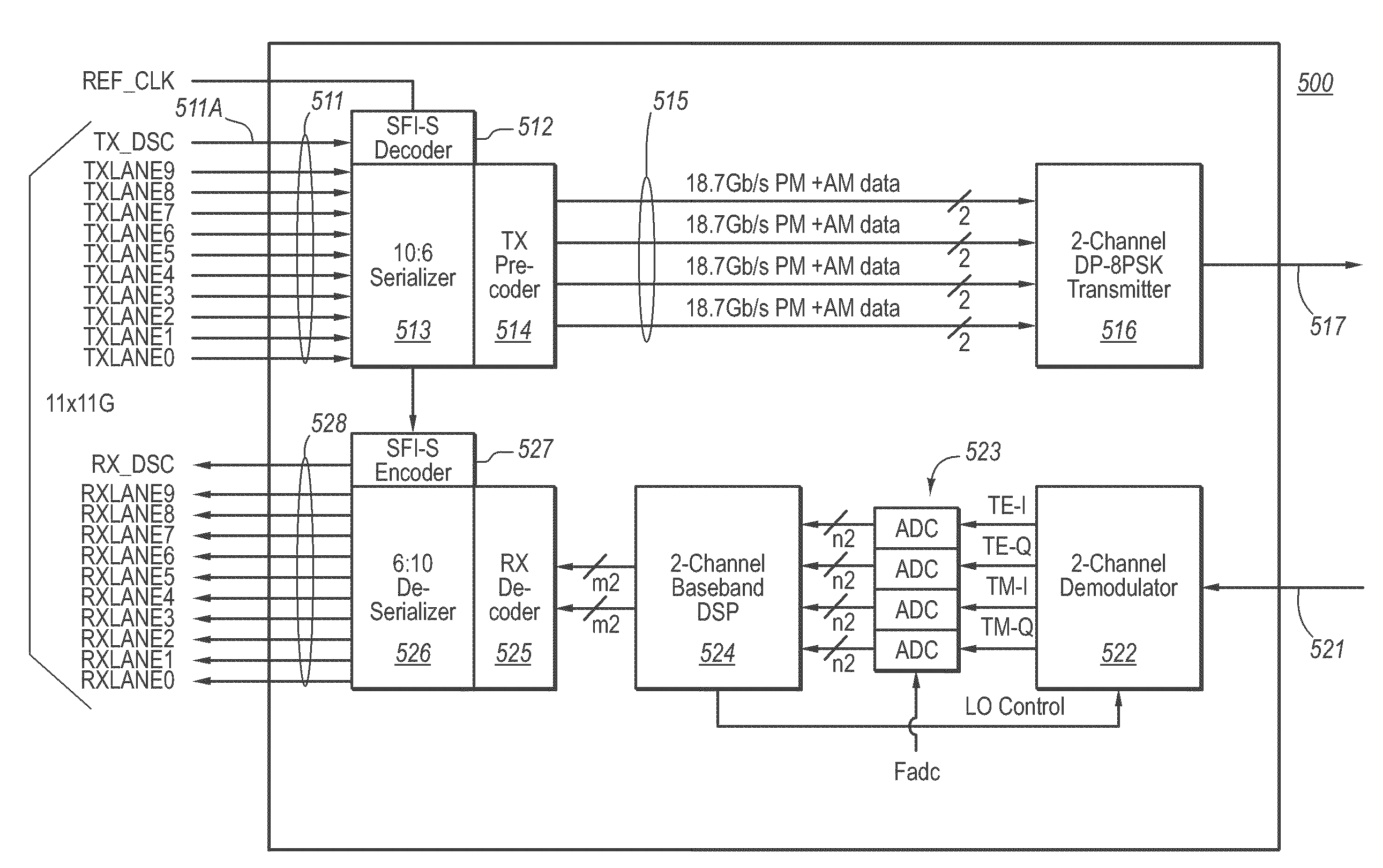
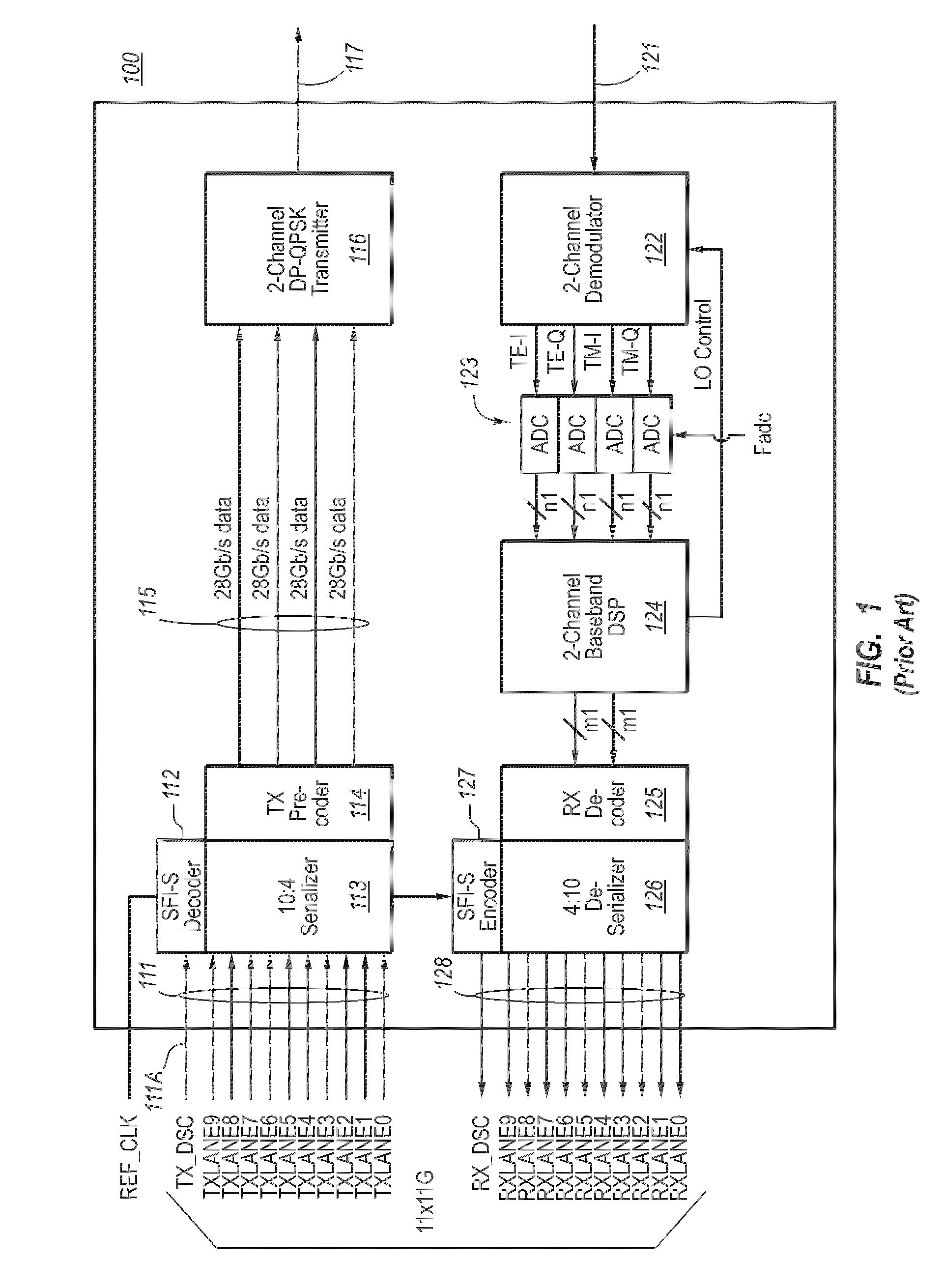
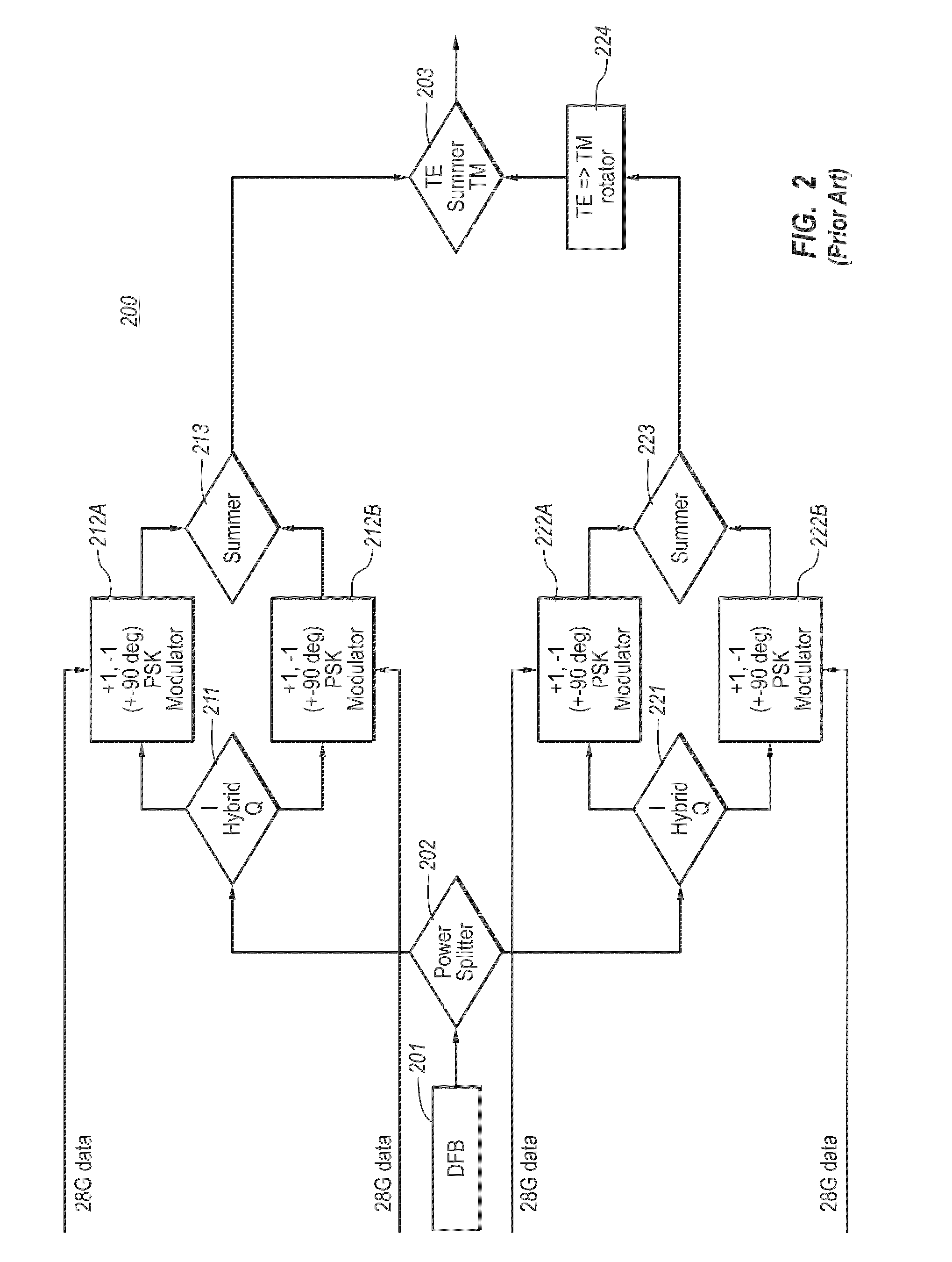
[0052]A high-speed optical transmitter and receiver structure are described herein. The high-speed optical transmitter comprises multiple digital lanes that are provided to a bank of digital-to-analog converters. The analog signals are then used to perform complex Phase Shift Keyed (PSK) modulation using both the in-phase and quadrature phase modulations, using a Chirp Managed Laser (CML)-based transmitter, and potentially using dual polarization (e.g., using the TE polarization and the TM polarization). A corresponding optical receiver receives the sequence of optical signals at a demodulator. For each polarization, the demodulator includes a corresponding demodulation channel that is configured to demodulate that polarization component of the optical signal into one or more analog signal components. Each of these analog signal components is converted into a corresponding digital signal using a corresponding analog-to-digital converter. The use of a CML transmitter may significantl...


PUM


Abstract

A high-speed optical transmitter comprises multiple digital lanes that are provided to a bank of digital-to-analog converters. The analog signals are then used to Phase Shift Keyed (PSK) modulation using a Chirp Managed Laser (CML)-based transmitter, and potentially using dual polarization. A corresponding optical receiver receives the sequence of optical signals at a demodulator. For each polarization, the demodulator includes a corresponding demodulation channel that is configured to demodulate that polarization component of the optical signal into one or more signal components. Each of these signal components is converted into a corresponding digital signal using a corresponding analog-to-digital converter. In the case of higher-order PSK modulation (e.g., 8PSK or higher), for each polarization, the analog converter has a lower sampling rate than for QPSK modulation.

Description

BACKGROUND OF THE INVENTION[0001]Communication technology has transformed our world. As the amount of information communicated over networks has increased, high speed transmission has become ever more critical. High speed communications often rely on the presence of high bandwidth capacity links between network nodes. For optical links, a transceiver module at one network node converts electrical data into optical data for transmission on the optical channel. At the other network node, another transceiver module receives the optical signal, and converts the signal into an electrical signal. Transceivers are equipped with transmit and receive channels, such that bi-directional communication is possible.[0002]Presently, standards are being developed for optical links at a staggering speed of 100 Gigabits per second (sometimes abbreviated as “100 G”). In fact, the Institute for Electrical and Electronics Engineers, Inc. (often referred to as “IEEE” for short), a leading professional as...

Claims


Application Information

Patent Timeline
IPC IPC(8): H04B10/12
CPCH04B10/40H04B10/532H04B10/69H04B10/58H04B10/5561
Inventor COLE, CHRISTOPHER R.MAHGEREFTEH, DANIELNGUYEN, THE'LINHSINGER, ANDREW C.SHANBHAG, NARESH RAMNATH
Owner II VI DELAWARE INC
Why Eureka
Try Eureka